A drywell is never the first choice for directing the flow of runoff. But in certain, well-defined cases, low-impact development calls for developers to dig deep.
Drywells are vertical, underground infiltration systems that receive runoff from impervious surfaces via buried pipes. Drywells reduce the rate, volume and temperature of runoff by infiltrating, or allowing the water to slowly seep, into the surrounding soils (BES 2006). Drywells also store a limited volume of runoff during storms.
These systems provide fewer benefits than other low-impact development measures. They also tend to be expensive to build and involve complicated permit processes. Because of these factors, drywells are generally chosen as a last resort when other tools such as rain gardens, planters, and porous pavements are not practical. By design, drywells are underground injection control (UIC) devices and will trigger state UIC requirements. (See Permits, page 6.)
In Oregon, drywells are commercially available in plastic or concrete, both of which consist of perforated manhole rings. In other areas of the country, there are designs that don’t use a prefabricated chamber, but instead fill the entire vertical excavation with storage aggregate and line it with geotextile fabric on all sides. While this isn’t a common practice in Oregon, it is permissible.
Site Conditions
Setbacks vary by jurisdiction. The City of Portland (BES 2008) requires a 5-foot setback from property lines and a 10-foot setback from building foundations. Additionally, drywells should be located 20 feet from cesspools and 500 feet from drinking wells (BES 2006, NRCS 2008, BES 2008). However, in eastern Oregon, where fractured bedrock can be shallow and many feet deep, drywells are often drilled into bedrock if the water table is sufficiently deep to allow positive drainage out of the drywell.
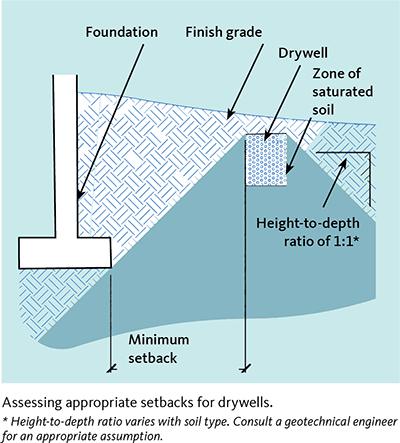
Since the small, plastic drywells are not as deep as the concrete drywells, Portland requires only an 8-foot setback from a building foundation rather than the standard 10 feet (BES 2008), and it’s possible that an even shorter setback could be permitted. A common guideline to determine an appropriate setback for infiltration facilities is to assume that water moves equally horizontally as it does vertically (in other words, that it moves in a 1H:1V ratio). An appropriate setback can be calculated by ensuring that the saturated zone of soil is outside the structural components of the building (Figure 2). Consult the state building codes and a geotechnical engineer to confirm how close your infiltration facilities can be situated to critical infrastructure.
Physical Setting
Impervious surfaces of varying types are acceptable. Areas of caution include those with minimally infiltrating soils, wellhead protection areas, and wastewater drainage areas (BES 2006). Flat slopes are preferred, and slopes of 20 percent or greater require geotechnical evidence prior to installation (NRCS 2008, PSMM 2008).
Since these are vertical systems with depths of up to 30 feet, they cannot be used in areas with high water tables. For roof runoff, the Oregon Department of Environmental Quality (ODEQ) requires 5 feet between the bottom of a drywell and the top of the seasonal high groundwater table, and 10 feet for all other runoff.
Other areas where infiltration should not occur include:
- Where the seasonal groundwater table is higher than 5 feet from the bottom of the facility for roof runoff, and 10 feet for other areas of runoff
- In contaminated soils and groundwater
- On slopes exceeding 10 percent or in landslide areas
- In potential stormwater hotspots (vehicle fueling areas, industrial loading, unloading, and material storage areas)
- Where bedrock is higher than 10 feet from the bottom of the facility.
Removing pollutants
According to some sources, drywells provide nominal water treatment. However, runoff from certain sources could pose a risk of groundwater contamination (NRCS 2008). If the runoff is from roads or parking areas, pair a drywell with a secondary water-quality facility. Based on published research, the Center for Watershed Protection estimated that the total amount of phosphorus to be removed is 60–93 percent, and nitrogen to be removed is 57–92 percent. However, this and other water-quality benefits are not recognized by ODEQ’s UIC program. See Permits, page 6.
Cost
Expenses depend on the size of the drywell, but in general, construction and maintenance of small residential facilities cost between $1,200 and $1,500 in 2010. The construction cost of larger concrete facilities was similar to the cost associated with installing a standard, deep manhole—around $10,000 to $15,000.
If runoff flows from a surface other than a rooftop, a water-quality facility will be required for pretreatment. When drywells are used in locations where other surface infiltration (non-UIC) facilities cannot fit, use proprietary treatment structures with filter cartridges to preserve water quality. These pretreatment systems range in cost from $6,000 to $25,000 installed, depending on the system and the amount of impervious area being treated. In addition, an annual maintenance contract to replace the filter cartridges, costing about $120 per year per cartridge, is also required.
Permitting costs for drywells vary from $100 to $300, and the cost of preparing the required permitting documentation can be as high as $2,000. Other expenses include the purchase of spill-response materials to be kept on site, and training in spill response measures for employees or maintenance staff.
One more factor affecting the bottom line: the potential cost of retrofitting existing drywells to meet the requirements of any future regulations enacted to protect Oregon’s groundwater resources; there are no grandfathering provisions in place for drywells (ODEQ 2010a).
Design
The design of drywells across the state depends on the volume of rainfall anticipated in each region.
Stormwater managers set standards for system capacity by measuring the intensity of precipitation over a period of time. A “design” storm is a theoretical storm that facilities such as drywells are designed to treat. The size of the storm is analyzed to occur at a given frequency. They are described as 6-month, 1-year, 2-year, 25-year or 100-year storms that occur over a 6-hour or 24-hour period. The size and duration of the design storm is typically specified by local regulations.
In Portland, where combined sewer overflows are the driving factor for infiltration requirements, managers use a 10-year, 24-hour design storm. In Eugene, planners determined that the 5-year, 24-hour design storm meets the city’s stormwater-management goals. Infiltration facilities are typically designed to capture and treat the stormwater runoff from surfaces draining to them during 80–90 percent of annual storm events, on average. This will often be a 1-inch, 24-hour design storm, but this volume probably will vary on the Oregon Coast. For jurisdictions with no standards, choose the minimum infiltration volume to prevent scouring of the downstream natural waterways. In Oregon, the 1- to 2-year, 24-hour design storm is the most widely used (FWS 2006). Check the Soil Conservation Service Storm Type map at http://extension.oregonstate.edu/stormwater/what-storm-type-do-you-live.
In some cases, cities may require drywells to infiltrate larger storm events, especially where local soils drain well or where the drywell has no overflow. Check with your local planning department for design requirements specific to your area.
Plantings at the surface are acceptable, but they must allow access for maintenance (BES 2006) and do not provide any water-quality benefit, since runoff is conveyed via a buried pipe underneath the plantings. Generally, uniformly graded drain rock with a minimum 30 percent void ratio is placed between the walls of the drywell and the filter fabric.
SIZING
Sizing of these facilities is based on the runoff volume they receive from both pervious and impervious surfaces. The amount of runoff routed to the drywell will depend on local rainfall patterns, the drainage area, and how much of the water runs off these surfaces. Drywells in Oregon are designed to drain in 24 to 36 hours where the rainfall pattern is small and frequent events (Type IA storm distribution) and 72 hours where rain events are more intense and less frequent (Type I or Type II storms).
The volume of runoff that a drywell is capable of infiltrating depends on the depth and diameter of the perforated rings and the infiltration rates of soils surrounding the facility.
For the small, plastic drywells, the authors recommend installing 1 unit per 500 square feet of impervious area, but this suggestion will vary with the infiltration rate of the soil.
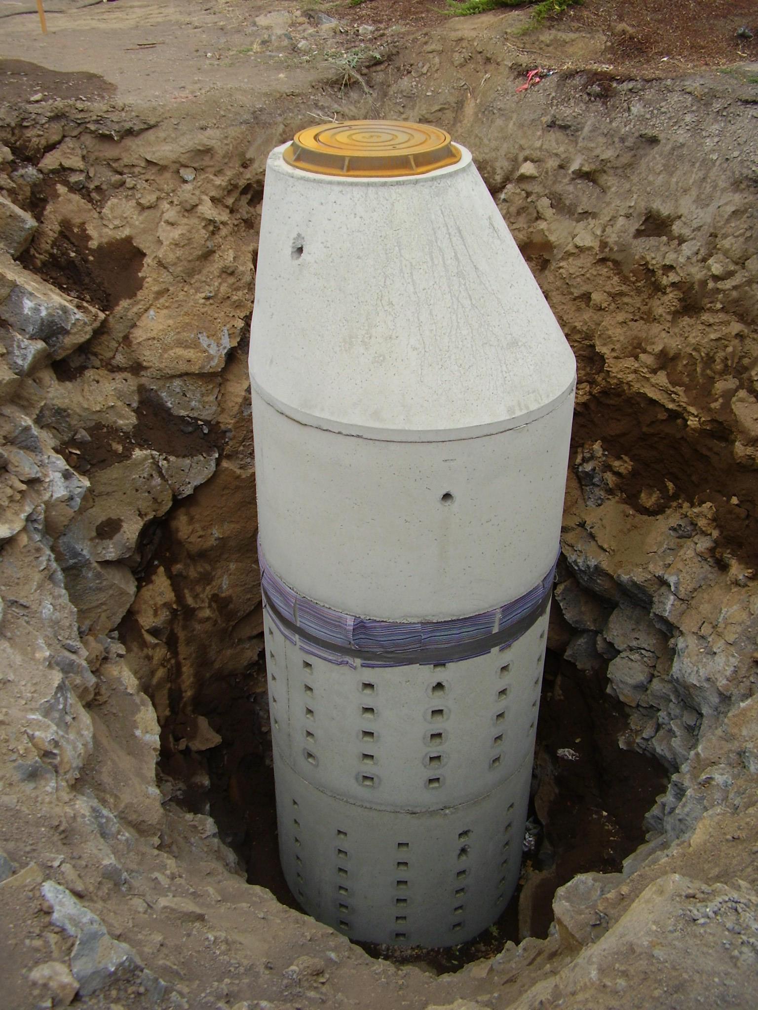
For runoff from large areas, a drywell is usually made from perforated concrete manhole rings installed vertically. Rings with a diameter of 4 feet are the most widely available. One foot of clean, washed, storage drain rock is usually placed around the outside of the drywell as backfill.
For runoff from small areas, a cost-effective variation of the concrete drywell is a mini drywell designed with polyolefin, a hard plastic. These facilities measure about 2 feet in diameter and 2 feet in depth, and their small size and light weight make them quite versatile. For both types, the drywell should be wrapped in nonwoven geotextile to prevent fine sediments from the surrounding soils from clogging it.
Typical drywell depths range from 2 to 20 feet. A few excavators can install drywells as deep as 30 feet, but 20 feet tends to be the maximum depth in most areas. If adequate disposal cannot be achieved by building the maximum depth of drywell in your area, drywells can be linked together in series by piping. Consult a civil engineer to model the stormwater runoff for your area and provide recommendations for drywell diameter, depth, number, and spacing.
SOILS
Because stormwater runoff is concentrated from a large area to a facility with a relatively small storage capacity, soils must drain well. Submit an infiltration test or bore log test for approval to your local jurisdiction (BES 2008). Soils may vary with depth; test samples on site and at a number of different depths to ensure that the facility will function as designed. See Infiltration Testing, EM 9214, https://catalog.extension.oregonstate.edu/em9214
Routing
Water must be treated prior to entering the drywell, and pretreatment mechanisms depend on the source of runoff. In most drywells, silt traps are used to prolong the life of the facility (BES 2008). For drywells collecting roof runoff, a silt basin is highly recommended, in addition to gutter screens to filter debris (NRCS 2008). For drywells capturing runoff from impervious areas other than residential roofs, employ proprietary treatment facilities with a filtering medium (BES 2006). A filtration rain garden or flow-through planter could also work.
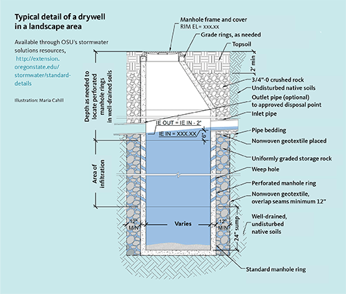
When the drywell reaches saturation, employ a bypass system. An overflow pipe can deposit runoff onto a splash block (NRCS 2008). Alternatively, it can deliver the excess runoff to a secondary facility (SEMCOG 2008). Excess runoff should never be directed to neighboring private property without a utility easement, nor should it be allowed to back up the system. The illustration on page 1 shows Portland’s standard residential installation, in which runoff from a large storm could back up and cause flooding. This flooding would occur at the point where the downspout connects to the drain pipe at finish grade, unless the rim of the catch basin, set lower than that elevation, is used as a large-storm relief valve.
Use an overflow pipe at the top of the facility or some other conveyance system to convey water to an approved disposal point. Another option is to lower the elevation of the overflow pipe (see illustration, page 4). Due to pipe cover regulations and topography, the overflow pipe may be too deep to daylight and require connecting to another pipe to route water off site. An approved disposal point is usually a public or private storm pipe, or an outfall location that won’t impact structures and other property.
Construction
To prevent clogging, provide erosion-control measures such as a compost sock and diversion methods. You may also consider staging construction of the drywell in such a way that the surrounding land is stabilized to prevent clogging (NJDEP 2004).
Drywell construction should disturb as little of the surrounding soil as possible. To avoid clogging the drywell during construction, at no time should runoff from other areas be directed to the drywell until those areas have been stabilized or fully constructed.
Follow these installation steps:
- Excavate a hole 2 feet larger in diameter than the outside diameter of the manhole rings. A clamshell is often used to excavate deep, narrow holes.
- Place the nonwoven geotextile fabric so that a continuous piece reaches the bottom and overlaps a minimum of 12 inches at the edges. It should be draped on all sides and to the bottom of the drywell. This geotextile will prevent fine sediments from migrating from the native soils to the surrounding drainage rock, and will help protect against long-term clogging.
- Place the solid, 3-foot-deep sump in the bottom and rearrange the geotextile if it has been pulled out of place. Position the rest of the specified number of perforated and nonperforated rings that will set the top ring at the correct finish grade.
- Install uniformly graded (that is, almost all the same size) drain rock between the outside walls of the drywell and the geotextile to the depth specified on plans. Dust or fine particles not washed away could clog the geotextile (Hicks and Lundy 1998), so not only should the base rock be delivered clean from the quarry, but it should also be washed carefully on site. One successful method is to hose the rock off in the delivery truck when it arrives. Another method might be to dump the rock and wash off the pile. In both instances, scooping of the rock should be done from the surface, and the rock should be closely monitored for fine sediments. As you work your way down the pile, fine sediments from above might only have been washed off partway through. If careful attention isn’t paid to this step, the geotextile fabric could become clogged with sediment, which would cause the drywell to fail.
- After rock has been placed a few inches above the highest perforated ring, lay the geotextile over the top of the rock and up the sides a few inches more, then trim it.
- Remove any debris that may have entered the drywell during construction.
- Install the lid and bolt it down.
Install inlet and outlet pipe by the same means used to connect pipes to standard manholes. Follow project specifications to backfill surface soil.
Maintenance
Properly maintained drywells can last decades. In the City of Gresham, maintenance has helped drywells last for more than 80 years. But once a facility clogs, it must be replaced (BES 2004).
Some maintenance tips:
- Remove excess debris, control erosion and trash, and maintain inlets and outlets.
- Remove vegetation that could clog inlets or outlets (BES 2006).
- Schedule frequent inspections in smaller facilities, less frequent inspections in larger facilities (NRCS 2008).
We recommend a design with a 3-foot-deep solid sump at the bottom to make suctioning excess sediment easier.
Permits
Drywells are considered a Class V Injection Well and must be approved by the ODEQ though the UIC permitting process. According to the U.S. Environmental Protection Agency, a Class V UIC well is, by definition, any bored, drilled, or driven shaft, or dug hole that is deeper than its widest surface dimension. These systems are regulated throughout the state because they don’t remove pollutants like rain gardens and swales do, and because they are much more likely to pollute groundwater due to their vertical nature. Special care must be taken to protect the groundwater by treating runoff first.
For roofs, the ODEQ doesn’t require any treatment. However, we recommend a silt basin that reduces sediment to protect against long-term clogging. In sensitive basins, additional treatment may be required since roofs may have a number of soluble pollutants, such as biological contaminants and hydrocarbons from asphalt shingles. Runoff from vehicular traffic requires more robust treatment.
In addition to the permitting paperwork, regulations call for a long-term stormwater management plan, including a description of the best management practices for the entire site, spill prevention and response, a maintenance plan and schedule, and an employee training record. The plan must be revisited every 5 years, or immediately after a spill, and the drywell itself must be reevaluated. The ODEQ has specific guidelines for pretreatment and other permitting requirements, which you can find on its website (ODEQ 2010a).
It’s worth noting that state rules prohibit the use of injection systems where better treatment or protection is an option, such as when a stormwater or municipal sewer is available. These services are considered available if the system is not at capacity or is within 300 feet of the site. (ODEQ 2010b). Facilities also fall under the requirements of the state Groundwater Quality Protection Act.
Most UICs fall under rule authorization, not permits. Individual residential roof drywells are not required to register and get ODEQ approval as UICs, unless the city requests the review because of high groundwater concerns. Fourplexes, apartment houses, commercial, and industrial roof drains do need ODEQ approval though rule authorization. Usually no pretreatment is necessary, as long as the discharge is only roof runoff. If the drywell serves a parking area, driveway, garbage bin, or loading dock, it needs to be registered and approved by ODEQ. Note that cities and counties cannot approve UICs; only ODEQ can do so as the agency designated by EPA.
If a drywell is to be decommissioned, follow a separate authorization process that includes testing, reporting, and additional paperwork.
Check with your local planning, engineering, or development services department for specific design requirements for your area.
References and resources
Arnold, J. A. (ed.), D. E. Line, S. W. Coffey, and J. Spooner. 1993. Stormwater Management Guidance Manual. Raleigh: North Carolina Cooperative Extension Service and North Carolina Division of Environmental Management.
Oregon Association of Clean Water Agencies. 2003. Underground Injection Wells for Stormwater, Best Management Practices. Retrieved from oracwa.org/pdf/ui-wells-for-SW-BMP-manual.pdf
City of Portland, Bureau of Environmental Services (BES). 2016. Portland Stormwater Management Manual. Retrieved from https://www.portlandoregon.gov/bes/71127.
City of Portland, Bureau of Environmental Services (BES). 2007. Standard Drawings, Precast Sump Standard Detail. Retrieved from https://www.portlandoregon.gov/transportation/article/640258
Center for Watershed Protection and Chesapeake Stormwater Network. 2008. Technical Memorandum: The Runoff Reduction Method. Ellicott City, MD.
Hicks, R. G., P. Curren, and J. R. Lundy. 1998, rev. 2003. Asphalt Paving Design Guide. Asphalt Pavement Association of Oregon.
Lower Columbia River Estuary Partnership. n.d. Lower Columbia River Field Guide to Water Quality Friendly Development: Techniques and Examples. Retrieved from www.lcrep.org/sites/default/files/fieldguide/techniques.htm
Natural Resources Conservation Service. 2008. “Urban BMP’s—Water Runoff Management.” Water Related Best Management Practices in the Landscape. Retrieved from www.wsi.nrcs.usda.gov/products/UrbanBMPs/water
New Jersey Department of Environmental Protection. 2004. New Jersey Stormwater Management Best Practices Manual. Retrieved from www.state.nj.us/dep/stormwater
Oregon Department of Environmental Quality. 2010a. Regulations. Water Quality, Underground Injection Control Program. Retrieved from http://www.oregon.gov/deq/wq/wqpermits/Pages/UIC-Regulations.aspx
Oregon Department of Environmental Quality. 2010b. Program Information. Water Quality, Underground Injection Control Program. Retrieved from http://www.oregon.gov/deq/wq/wqpermits/Pages/UIC.aspx
Southeast Michigan Council of Governments. 2008. Low Impact Development Manual for Michigan: A Design Guide for Implementers and Reviewers. Retrieved from https://www.semcog.org/desktopmodules/SEMCOG.Publications/GetFile. ashx?filename=LowImpactDevelopmentManualforMichiganSeptember2008.pdf
U.S. Fish and Wildife Service. 2006. Gravel Mining: Sediment Removal from Active Stream Channels in Oregon. Retrieved from http://www.fws.gov/oregonfwo/ExternalAffairs/Topics
© 2018 Oregon State University.
About the authors