Stormwater planters are a lot like rain gardens: They are designed to capture runoff and filter out sediment and pollutants. The difference? Stormwater planters are contained in structures made of a durable material, such as plastic-lined wood, stone, brick, or concrete. Stormwater planters have been described as “rain gardens in a box.”
Runoff is piped, channeled, or directed by overland flow to the surface of the planter, where it is temporarily stored. Water may then be allowed to infiltrate (seep) into the soil, or it may be conveyed to another approved disposal point.
As in rain gardens, there are two kinds of planters: infiltration and filtration. Infiltration planters cleanse, detain, and reduce runoff volumes by allowing water to soak into the surrounding soils. By contrast, filtration planters cleanse and detain stormwater runoff and then pipe the water off-site. They do not allow infiltration and do not significantly reduce stormwater volumes. In fact, they are lined specifically to prevent infiltration in unsafe conditions.
Let’s explore what goes into these “rain gardens in a box” and when you might want to use one in your project.
Site conditions
Stormwater planters are often in the public right-of-way (DES and CEDD 2007). They are also often built on private sites where space available for stormwater management is limited.
The main advantage of planters over rain gardens is that the structure allows more water to be stored, which reduces the footprint of the facility. The main drawback is that the vertical sides must be constructed out of concrete, wood, or some other material, which costs more to build. Potential areas for planters include front and back residential yards, parking lots, and streets (Barr 2001).
Infiltration and filtration planters can be modified to fit almost any physical setting, and so are optimal alternatives for sites with conditions that restrict the use of other best management practices. Because of their flexible location requirements and range of designs, planters can add aesthetic appeal to a landscape, and can also attract wildlife (LCREP 2006). Planters can also fulfill certain landscaping requirements on a site.
Filtration vs. infiltration planters
Filtration planters with liners can be used anywhere, but an improperly designed infiltration planter has the potential to contaminate groundwater, destabilize slopes, or undermine foundations.
Use a filtration planter instead of an infiltration planter in these instances:
- Where the seasonal high groundwater table is closer than 24 inches from the bottom of the facility;
- Where bedrock is closer than 18 inches from the bottom of the facility;
- At a horizontal distance greater than 5 feet from underground utilities
- In areas of new fill (placed fewer than five years ago) that is heavily compacted to stay in place;
- In areas with contaminated soils or groundwater;
- Within 100 feet of a well;
- In potential stormwater hotspots (vehicle fueling areas or industrial loading, unloading, and material storage areas);
- On slopes exceeding 10 percent or in landslide areas;
- Over karst bedrock (landscape underlain by eroded limestone);
- In possible spill areas; and
- Where the stormwater facility cannot be placed more than 10 feet from a building, under roof spouts or the top of any other wall footing; or In any location designated by a qualified licensed engineer or geologist who has signed and stamped a geotechnical report, site plan or letter.
Removing pollutants
Stormwater planters are an appropriate tool to manage runoff from all types of impervious surfaces (DES and CEDD 2007). Storing runoff within the planter allows sediments and pollutants to settle out. Plantings also clean water through a process known as bioretention. Infiltration planters effectively reduce stormwater flow rates and volumes, which decreases the amount of runoff and pollutants entering waterways.
Based on published research, the Center for Watershed Protection estimates that stormwater planters remove an average concentration of 25 to 50 percent of phosphorus and 40 to 60 percent of the nitrogen present in runoff (CWP 2008). Runoff itself was reduced by an estimated 40 to 80 percent. Find more information on pollutant removal in table SQ-6 in the Urban Drainage and Flood Control District’s Drainage Criteria Manual (UDFCD 2008).
Cost
Planter costs vary by size, site conditions, and vegetation, and are generally used only where sites are too constrained to build a rain garden. The structural requirement of creating vertical walls makes this system one of the most expensive facilities to build. Filtration planters are more costly than infiltration planters, due to piping requirements and waterproofing concerns, since they are often constructed close to buildings or other structures.
If a planter has no pretreatment, maintenance costs vary with the choice of long-term erosion control—compost mulch, rock mulch, or dense vegetation—since the mulch option will probably be removed with the sediment and have to be replaced. Rock mulch costs more up front than compost mulch and is more expensive to maintain.
Design
Infiltration and filtration planters
The amount of runoff routed to the planter depends on local rainfall patterns, the area of surfaces draining to the planter, and the volume of water that runs off these surfaces. Impervious surfaces generate the most runoff; simple landscapes such as lawn generate a moderate amount of runoff; and complex garden areas with trees, shrubs, and mulch generate the least, if any, runoff.
To properly size both types of planters, account for the amount of runoff routed to it, ponding depth (the depth allowed for the water to pond before overflowing the garden), and the infiltration rate (a measure of how fast water soaks into the native soils). Ponding depth is typically 12 inches between the top of the amended planting soil and the overflow outlet (DES and CEDD 2007, BES 2016). The slope of the bottom of the facility should not exceed 0.5 percent (LCREP 2006).
Stormwater planters have vertical or near-vertical walls and should be designed in such a way that no two adjacent grades, or elevations, differ by more than 30 inches. According to Oregon law, if you exceed this measurement, you must include a handrail or some other barrier adequate for fall protection.
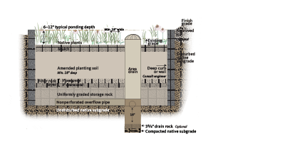
Infiltration planters: sizing and design
A general rule is that infiltration facilities, such as infiltration stormwater planters, manage runoff up to 10,000 to 15,000 square feet of impervious drainage area (4 to 15 percent of the impervious surfaces draining to it) or the equivalent in landscape area (approximately 11,750 to 17,500 square feet). Check with your local planning department for design requirements specific to your area.
The design of stormwater planters varies at different locales throughout Oregon, with wetter regions generally requiring more infiltration capacity (larger footprints or faster infiltration rates) than drier regions. Rainfall patterns vary, over time, in volume and intensity. To help quantify these patterns, it’s helpful to understand the concepts of a “design” storm and rainfall distribution.
Stormwater managers set standards for system capacity by measuring the intensity of precipitation over a period of time. A “design” storm is a theoretical storm that facilities such as stormwater planters are designed to treat. The size of the storm is analyzed to occur at a given frequency. They are described as 6-month, 1-year, 2-year, 25-year, or 100-year storms that occur over a 6-hour or 24-hour period. The size and duration of the design storm is typically specified by local regulations.
Planters are typically designed to capture and treat the stormwater runoff from surfaces draining to them during 80 to 95 percent of annual storm events, on average. In Oregon, this is a 24-hour design storm somewhere between 1 and 2 inches. Even if a jurisdiction requires infiltration of the 25-year storm event, stormwater planters are still a good choice as long as soils drain reasonably well. Table 1 (page 5) shows approximately how large a 12-inch deep stormwater planter would need to be in cities around Oregon, assuming a drainage area of 10,000 square feet and a design infiltration rate of 2 inches per hour.
A rainfall distribution is a statistical representation of the intensity and duration of rainfall that occurs on average for each storm. These distributions provide a way to model the intensity and duration of rainfall for a given design storm. Oregon has three different rainfall distributions, called Type IA, Type I, and Type II. Type IA is a lower intensity, longer duration storm typical of western Oregon, while Type II storms are higher intensity, shorter duration storms. Type I storms fall in between these two. Each jurisdiction will develop its own requirements for the size of storm (design storm) and distribution type (1A, 1, and II) based on goals for water quality and quantity.
In Oregon, infiltration planters are designed to drain through the soil within 30 hours for a Type IA storm distribution, 72 hours for Type I and Type II storm distributions, and to bypass the soil during storms larger than the design storm. The suggested minimum width for infiltration stormwater planters is 24 inches, measured within the walls (BES 2016). These sizing recommendations ensure that they will drain in time to treat the next storm, provide drainage for plants, and prevent the accumulation of standing water (a draw for mosquitoes and other pests). Peak flows from the 25-year storm event can be infiltrated in cost-effective facilities throughout the state, regardless of whether your jurisdiction experiences the gentle, frequent Type IA storm distribution or the less frequent, more intense Type II storms, or something in between.
Slower infiltration rates necessitate larger planter footprints than those represented in Table 1 if treating the same size storm. Keep in mind that most jurisdictions do not require treatment of that large of a storm (a 25-year storm), so if the design storm is smaller, then the facility footprints illustrated in Table 1 might be larger than your final design. (See the column labeled “Stormwater planter footprint needed.”) Some regulations vary for other reasons. For example, the Central Oregon Stormwater Manual requires the area of the planter to be based on storing the volume of the entire water quality storm—a much shallower and more frequent storm than the 25-year, 24-hour design storm—since the soil may be frozen and unable to infiltrate during some storms. Given the same set of variables, these planters will be larger than those shown in Table 1.
Once size is determined, make sure that the opening width of the planter is equal to or wider than the depth of the planter. If the facility cannot be sized to accommodate the required runoff volumes, place a 12-inch layer of washed drain rock beneath the infiltration planter.
Designers may also choose to use an underdrain with an infiltration planter, although that option prevents water from soaking into the soil unless the pipe is raised up off the bottom a little or connected to a catch basin with a weir or other control structure that forces water to back up in the stormwater planter and infiltrate before overflowing. See page 8 for recommendations on designing an infiltration planter to avoid triggering state underground injection control (UIC) requirements.
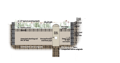
Filtration planters: sizing and design
Filtration planters can be smaller than infiltration planters because their chief purpose is treating runoff from small, frequent water-quality storms; they are not designed to infiltrate large quantities of runoff. In situations where water should be prevented from infiltrating the underlying soils, use an impermeable liner along the bottom of the facility. These liners typically consist of 60-mil PVC (DES and CEDD 2007), but 30-mil polyethylene pond liners and bentonite clay mats can be just as effective. As in infiltration planters, the suggested minimum width is 18 inches, measured within the walls (BES 2008). Typically, a 12-inch layer of ¾-inch open-graded (that is, all the same or of very similar diameter), washed, crushed aggregate is used in combination with a perforated, 4-inch HDPE (high-density polyethylene) pipe to allow for detention and conveyance of the water (Gresham 2007). The City of Portland recommends a layer of ¾- to ¼-inch washed, crushed rock between the soil medium and gravel layer to prevent soil from mixing with the drain rock (BES 2008). However, studies indicate a detention time of only 13 minutes and a reduction in volume of only 20 percent for ½-inch, 24-hour storms in our rainy season’s early storms, when soils are not saturated (Yeakley 2010). Thus, it may not be advisable to rely on filtration planters for flow control or detention purposes.
Some jurisdictions require the use of a geotextile filter fabric instead of rocks. If not required, we recommend using washed, crushed rock to limit the amount of “fines” (silt, fine sand) that are transported and could clog a geotextile. Clogged geotextile fabrics keep stormwater from reaching the gravel layer below and inhibit proper flow out of the facility, causing the plants to have constant “wet feet.” Designers can slow the water a little by installing a narrow, French drain underdrain rather than installing gravel across the entire bottom of the facility.
Soils and medium
Planters are generally filled with amended planting soils and topped with mulch. Infiltration planters also use native, uncompacted soils at the base. Many planter details call for a 2-inch layer of bark mulch to cover the facility. However, this material can float and leave soil bare, even during small storms that simply redistribute the mulch around the garden; large storms may carry it right out through the overflow structure. As mulch breaks down, the amount of available oxygen in the downstream water body can decrease. For this reason, use a 2-inch layer of coarse compost or arborist wood chips in lieu of bark mulch in the regularly inundated area. Above the regularly inundated area, either continue with coarse compost or switch to fine compost. Consider adding mycorrhizae (that is, live mushroom soil additive, not mushroom compost) to the soil, which grow into the compost and form a mat of mycelium, or mushroom roots, that hold it together and keep it from floating.
Since a planter is routinely inundated, soil can easily erode. The most effective way to control erosion is to plant dense vegetation on the bottoms of the facilities, and reserve the use of mulch for the time of construction. Dense plantings also shade out most weeds. Avoid rock mulch, which is expensive and difficult to maintain without causing the rocks to settle into the growing medium. The placement of rock mulch at the inlet and outlet is also inadvisable, since high water flows bury it in sediment and transport smaller rocks, up to 2 inches in diameter, around the facility, leaving soil bare.
Use amended planting soil or amended native soils with infiltration rates that are high enough to pass the design storm through the soil, but not so high that the stormwater does not spend enough time in the soil for treatment (the retention time). The ideal infiltration rate is between ½ inch per hour and 12 inches per hour (PSP 2009). The top 18 inches of soil is typically amended with organic compost. In some cases, existing topsoil is replaced with a soil mix, as specified by the local jurisdiction. Avoid mixes that are so sandy that they do not have enough organic matter to adequately support plant life, which increases irrigation and fertilization needs and the likelihood the plants will die. Also, be careful to use soil and compost that are free of weed seeds. Other key considerations for robust plant establishment and stormwater treatment by plants and purchased soil mixes include soil pH (between 5.5 and 7.5) and cation-exchange capacity (less than 5 millequivalents/100 grams) (LIDC 2003), which the supplier should be able to confirm.
Test native soils in the proposed infiltration planter location at the design depth (or as close to that depth as possible) to determine the infiltration rate of the native undisturbed soils below the amended topsoil (see Infiltration Testing, EM 9214). The effective infiltration rate of the facility is defined by the area available for infiltration: The larger the infiltration area, the lower the soil’s infiltration rate can be while still managing the required storm. Most jurisdictions recommend at least ½ inch per hour when using an infiltration facility, but the rate could be less if space and budget allow. Since stormwater has already passed through the middle, 18-inch-deep amended soil layer and received treatment, there is no recommended maximum infiltration rate for native soils. If infiltration rates are so low that the plants will be inundated for too long, consider using an infiltration stormwater planter with an underdrain. Install it so it’s raised a few inches above the bottom of the drain rock to allow some water to infiltrate out the bottom of the facility. Even a little infiltration helps improve water quality and reduce downstream flooding, but be aware that underdrains are notorious for exporting nitrogen and phosphorus, which cause algae blooms. For this reason, a planter with a bigger area and smaller ponding depth is a better choice than an underdrain.
Storage rock
Some facilities sited on soils with lower infiltration rates require storage rock to store runoff before infiltration or conveyance. However, this practice is questionable, especially if the storage rock is separated from the surrounding native soil by a geotextile fabric, which can clog. Instead of a fabric, use a granular subbase material meeting gradation requirements of AASHTO 3 or 4 aggregate, which is a specification for uniformly graded gravel (UDFCD 2008). Avoid rounded river rock, which is usually mined out of riverbeds in Oregon; mining activities damage those waterways.
Vegetation
The interaction of soil, plants, and the beneficial microbes that concentrate on plant roots is what ultimately provides the treatment benefit of planters. To make full use of this benefit, a facility designed with more plants will result in greater treatment capacity.
A variety of trees, shrubs, grasses, and ground covers may be used in both sun and shade conditions. Plant densely to maximize runoff treatment and control weeds; aim for 90 to 95 percent coverage within two to three years. Local jurisdictions often provide specifications for density, size, and types of vegetation. Choose plants based on their tolerance to flooding and ability to survive in local climate conditions with no fertilizers, herbicides, or insecticides. Plants should also be able to survive with minimum to no watering after establishment, which usually occurs in three years.
Design planters to fit into the landscape. Perennial flowers, ornamental grasses, and shrubs can add significant appeal. Planters can also be designed to attract beneficial insects and wildlife. Contact your local OSU Extension Service office or planning department for a list of plants appropriate for your area.
Be careful to avoid planting noxious weeds or invasive species. Floods can carry weed seeds downstream to natural wetlands. A list of noxious weeds is available on the Oregon Department of Agriculture’s website (ODA 2007).
Whenever possible, choose native plants. Nonnative seeds and rhizomes can greatly impact the habitat potential and hydrology of our natural waterways. In addition, native plants support native microbes and other native soil life and are a better food source for native insects and birds. If your jurisdiction does not have plant recommendations, contact the local soil and conservation district or visit the USDA PLANTS database (plants.usda.gov) and use the Advanced Search option to generate your own list. The Washington Department of Ecology provides an extensive list of plants adapted for climates east of the Cascades (WDOE 2013).
In cold climates, planters and other bioretention facilities may be used for snow storage or to treat runoff from an area that was treated with salt as a deicer. In these cases, choose salt-tolerant, non-woody species (EPA 2013.)
Routing
Both infiltration and filtration stormwater planters should have an overflow structure or other means to handle large storms. Use a freeboard (the depth from the maximum ponding depth to the top of the facility) of at least 2 inches (BES 2016). Beehive grates or U-shaped overflows make good overflow devices because they are less likely to clog than a flat catch-basin grate, but the U-shaped grates are commonly placed at too high an elevation. Make sure that if you use this system, the bottom of the pipe, not the top, is set to ensure adequate freeboard of at least 2 inches below the top of the facility. Another strategy when a standard catch basin is already available in the street is to direct overflows safely to the public right-of-way via a weir or berm. Regardless, overflow should drain to an approved disposal point.
In filtration planters, the overflow device is connected to a perforated pipe in the gravel bed below. This perforated pipe allows water to drain through and be treated by the soil column and then conveyed away so plants do not become waterlogged. If the facility is lined, the perforated pipe is completely enclosed in the facility and cannot infiltrate to the native soils, and so is not regulated as an Underground Injection Control (UIC). Perforated pipes that do not drain to an approved disposal point, such as a surface infiltration facility or a nonperforated pipe, may trigger UIC requirements and are reviewed on a case-by-case basis.
For nonperforated overflow pipe sizing, see the Oregon Plumbing Code at oregon.gov/BCD/pages/index.aspx. Oregon public facilities in streets require 6- or 8-inch ASTM 3034 SDR 35 PVC pipe. Private facilities require cast-iron ABS SCH40, or PVC SCH40 (BES 2016). Outlet size should be selected to drain the planter over 12 hours or more (UDFCD 2008) and should be of sufficient diameter that it can be cleaned and maintained with the equipment available.
Construction
As with all stormwater management facilities, take special care to properly construct an infiltration planter. Since we rely on the native subgrade soils to infiltrate stormwater, use orange protection or chain-link fence to mark planter areas off-limits to construction traffic and stockpiling activities. Use construction techniques that protect the soils during excavation, such as track equipment or excavating from the sides of the infiltration area. If the soils are exposed to rain, fine soil particles that may clog the native subgrade soils will be picked up and moved around. On a dry day, rake the surface to a depth of 3 inches to loosen soil before proceeding, or fold a few inches of compost into 8 to 12 inches of soil using a garden spade.
Once the native subgrade has been exposed, install a rock filter (Detail, page 2) to preserve the voids in the overlying gravel storage rock (SEMCOG 2008) if the design includes rock storage. Next, install the storage rock, if needed. Place the planting medium in 6-inch lifts and compact it lightly with boot tamping or water compaction to avoid settlement after the first storm. Never use vibratory compaction, which could negatively impact the many benefits the soil provides.
Next, place the mulch. Give plants at least three months to establish themselves before allowing stormwater to flow to the facility. Given this time, the plant roots will have a better hold on the soil, decreasing the effects of erosion, and increasing the odds that the plants will grow and thrive.
Maintenance
Maintenance requirements are typical of landscape areas, but be sure to factor in additional work for mechanical structures, such as pipes, inlets and outlets. If properly maintained, a stormwater planter can last indefinitely (Barr 2001). If the facility receives large volumes of silt and clay during storms, or small volumes over time, it could become clogged. Use a pretreatment structure at the inlet to settle out sediments before stormwater enters the facility.
Maintenance demands are typically heavier in the first three years. Plants may need frequent watering and weeding to survive Oregon’s dry summers until they are well established and cover at least 90 percent of the bottom of the facility. Maintenance needs taper off dramatically if you choose plants that require little to no watering after establishment and tolerate flooding conditions. Keep weeds down by providing only the amount of irrigation needed, and no more. Because these systems are not very effective at treating soluble pollutants such as nitrogen and phosphorous, practice integrated pest management. Do not use herbicides or pesticides in the facility itself.
Inspect the facility after major storm events and tend to it as needed.
Typical maintenance:
- Remove sediment and debris and replace mulch (this could be a frequent requirement if the facility design doesn’t include a pretreatment).
- Clean and repair inlets and outlets, embankments, and berm dams. Control erosion. Replant as necessary.
- Remove weeds by hand.
Permits
Consult your local planning and building department, and ask about the applicable permits, plumbing codes, and piping requirements. Find out if there are any maps, as-built drawings, or site-specific constraints. In many cases, when building a planter on a nonresidential site, a commercial building permit is required. A clearing, grading, and erosion-control permit may be required if the area of ground disturbance is large enough (LCREP 2006). Permitting requirements may depend on the design of the facility.
UIC regulations
A Class V Underground Injection Control is a system designed for the subsurface placement of fluids and is regulated through the Oregon Department of Environmental Quality’s (ODEQ) UIC program. This program protects groundwater resources from injection of pollutants directly underground.
The U.S. Environmental Protection Agency defines a Class V UIC well as any bored, drilled, or driven shaft; a dug hole whose depth is greater than its largest surface dimension; an improved sinkhole; or a subsurface fluid distribution system (an assemblage of perforated pipes or drain tiles used to distribute fluids below the surface of the ground). The following guidelines are for designers who are considering a stormwater planter to treat runoff before discharging it to surface water. These suggestions will help avoid triggering UIC requirements in the design of a stormwater planter. If a stormwater planter is being considered for pretreating runoff before discharging it to a UIC, the designer should contact ODEQ’s UIC program during early planning stages, as this is considered part of the UIC system and must be authorized as an assembly.
An infiltration planter designed and installed following the details shown on page 3 is not considered a UIC if the discharge point is to surface water. However, changes to the design that would allow runoff to shortcut infiltration through the top of the facility could turn the facility into a UIC. Also, when sizing an infiltration planter, avoid designing a facility that is deeper than the widest surface dimension. It would not be a UIC if excess runoff is routed to a stormwater conveyance system that discharges to surface water. Finally, conveying runoff to the surface of an infiltration planter and routing the excess runoff to surface water will help you avoid triggering state UIC requirements.
A filtration planter is not a UIC because, by design, it does not infiltrate. Instead, it filters runoff through mulch and amended soil mix. This filtered runoff is then routed via a nonperforated overflow pipe and ultimately to a stormwater conveyance system discharging to surface water. For more information on low-impact development and UICs, see the ODEQ fact sheet “Identifying an Underground Injection Control” (ODEQ 2015).
References and resources
Barr Engineering Company. 2001. Minnesota Urban Small Sites BMP Manual: Stormwater Best Management Practices for Cold Climates. Metropolitan Council Environmental Services, St. Paul, MN. Accessed from https://www.pca.state.mn.us/water/stormwater-best-management-practices-manual
Center for Watershed Protection (CWP) and Chesapeake Stormwater Network (CSN). 2008. Technical Memorandum: The Runoff Reduction Method. Ellicott City, MD.
City of Gresham: Department of Environmental Services and Community and Economic Development Department (DES and CEDD). 2007. Green Development Practices for Stormwater Management: An Implementation Guide for Development Projects in the Pleasant Valley and Springwater Plan Districts.
City of Portland: Bureau of Environmental Services (BES). 2016. Portland Stormwater Management Manual.
Hicks, P. C., and J. R. Lundy. 1998 (Dec. 30). Asphalt Pavement Design Guide. Asphalt Pavement Association of Oregon.
Lower Columbia River Estuary Partnership (LCREP). 2006. Lower Columbia River Field Guide to Water Quality Friendly Development. Prepared by City of Portland: Bureau of Environmental Services. Accessed from http://www.estuarypartnership.org/sites/default/files/fieldguide/index.htm. (WS 0603)
Low Impact Development Center, Inc. (LIDC). 2003. Drainage—Bioretention Specification. Beltsville, MD. Accessed from https://www.lid-stormwater.net/biolowres_specs.htm
New York State Department of Environmental Conservation (NYDEC). 2007. “Chapter 9: Redevelopment Projects” in New York State Stormwater Management Design Manual. Prepared by Center for Watershed Protection, Ellicott City, MD.
Oregon Department of Agriculture (ODA). 2007. State noxious weed list and quarantine. In ODA Plant Division, Noxious Weed Control. Salem, OR. Accessed from www.oregon.gov/ODA/PLANT/WEEDS/lists.shtml
Southeast Michigan Council Of Governments (SEMCOG). 2008. Low Impact Development Manual for Michigan: A design guide for implementers and reviewers. Detroit, MI.
Oregon Department of Environmental Quality (ODEQ). 2015. Fact Sheet: Identifying an Underground Injection Control. Portland, OR. Accessed from www.oregon.gov/deq/FilterDocs/IDswInjSysFS.pdf
Puget Sound Partnership (PSP). 2009. Technical Memorandum: Bioretention Soil Mix Review and Recommendations for Western Washington. Prepared by C. Hinman for Pierce County Extension, Tacoma, WA. Accessed from http://citeseerx.ist.psu.edu/viewdoc/download;jsessionid=8E31F0BA0ADEE99D4026F62D1954E528?doi=10.1.1.431.4124&rep=rep1&type=pdf
University of New Hampshire: Stormwater Center (UNHSC). (n.d.). Bioretention System (Bio II). Accessed from https://www.unh.edu/unhsc/sites/unh.edu.unhsc/files/pubs_specs_info/2009_unhsc_report.pdf
Urban Drainage and Flood Control District (UDFCD). 1999, rev. 2008. Drainage Criteria Manual (Vol 3). Denver, CO.
Washington Department of Ecology, 2013. Eastern Washington Low Impact Development Guidance Manual. Pub no. 13-10-036. https://fortress.wa.gov/ecy/publications/SummaryPages/1310036.html
Yeakley, Alan and Norton, Kate (Yeakley). 2010. “Assessment of rainwater detention structures for an urban development in Wilsonville, Oregon” presented at the Urban Ecology and Conservation Symposium, Jan. 25, 2010.

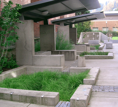
Photo: Bureau of Environmental Services
Stormwater planter at Epler Hall at Portland State University.
Maria Cahill, principal, Green Girl Land Development Solutions; Derek Godwin, watershed management faculty, professor, Biological and Ecological Engineering, College of Agricultural Sciences, Oregon State University; Jenna H. Tilt, assistant professor (senior research), College of Earth, Ocean, and Atmospheric Sciences, Oregon State University
EM 9213
June 2018
Filtration planter
|
25-year event depth |
Distribution |
Peak flow (cfs) |
Stormwater planter footprint needed (square feet) |
Percentage of facility size compared to impervious drainage area |
Peak flow exceeding planter storage (cfs) |
|
|
Salem |
4 |
Type IA |
0.22 |
784 |
7.8% |
0 |
|
Coos Bay |
5.5 |
Type IA |
0.30 |
1089 |
10.9% |
0 |
|
Redmond |
1.8 |
Type I |
0.29 |
431 |
4.3% |
0 |
|
Wasco |
2.3 |
Type I |
0.38 |
552 |
5.5% |
0 |
|
La Grande |
2.4 |
Type II |
0.78 |
812 |
8.1% |
0 |
|
Pendleton |
1.6 |
Type II |
0.51 |
529 |
5.3% |
0 |
|
Table 1. Peak flow comparison and sizing examples from modeling results to infiltrate runoff from 10,000 square feet of impervious area at a rate of 2 inches/hour during the 25-year, 24-hour design storm |
||||||
© 2018 Oregon State University.
Extension work is a cooperative program of Oregon State University, the U.S. Department of Agriculture, and Oregon counties. Oregon State University Extension Service offers educational programs, activities, and materials without discrimination on the basis of race, color, national origin, religion, sex, gender identity (including gender expression), sexual orientation, disability, age, marital status, familial/parental status, income derived from a public assistance program, political beliefs, genetic information, veteran’s status, reprisal or retaliation for prior civil rights activity. (Not all prohibited bases apply to all programs.) Oregon State University Extension Service is an AA/EOE/Veterans/Disabled.
About the authors