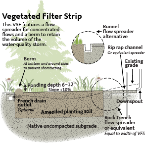
In managing runoff, one cost-effective tool developers use is a gently sloping filtering facility known as a vegetated filter strip, or VFS.
VFSs manage smaller volumes of runoff and are designed to slow the speed of runoff, filter pollutants, and collect sediment before passing the remaining runoff to a secondary facility, such as a swale. They can also be designed like rain gardens with amended soils to store runoff and allow it to seep, or infiltrate, into the soil, but they have no storage pond.
Traditionally, VFSs have been used in agricultural settings to filter sediment and bacteria from surface runoff and protect stream water quality. Today, they are becoming more prevalent in neighborhoods, towns, cities, highways and other urbanized areas.
If designed correctly and with the right mix of healthy plants, a VFS can be a low-maintenance, relatively inexpensive option.
Site conditions
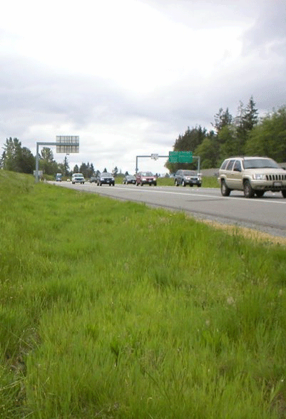
VFSs need space, which means they may not be ideal for developed properties that are undergoing a stormwater retrofit (Barr 2001). They can, however, help meet open-space requirements in new developments (UDFCD 2008). Ideal locations for VFSs are along roads, highways, and at roof downspouts, as well as adjacent to small parking lots and other pervious surfaces (Barr 2001, Field 2007). An alternative location could be the center of a driveway, usually 3 feet wide with two 3-foot aisles of paved driveway. The paved portions slope slightly toward the center filter strip (PSMM 2008). VFSs can also be located along a stream as the outer zone of a stream buffer (Field 2007). When placing a facility, consider the potential for groundwater contamination, especially if the facility is located in urban or other areas with high pollutant levels in runoff (Barr 2001, Field 2007).
Use a vegetated filter strip designed to infiltrate in these instances:
- Where the seasonal-high groundwater table is lower than 24 inches from the bottom of VFS;
- Where the bedrock is lower than 18 inches from the bottom of the VFS;
- 10 feet from a building with a basement;
- 2 feet from a building without a basement (that is, slab on grade, crawl space, pier, or post foundations);
- Downhill of pervious areas with a maximum flow path of 150 feet;
- In existing forested areas, with some exceptions. Note that additional volumes of water can harm the health of established trees, especially Oregon white oak. Some species that can tolerate additional water after establishment include willow, ash, alder, poplar, and some maples. Consult with an International Society of Arboriculture Certified Arborist® if you have questions about tree species’ water tolerance level.
- On slopes of less than 15 percent, except where that slope is a historical site or has been found not to be a landslide hazard by a licensed geotechnical engineer or licensed geologist; and
- In any location designated by a qualified licensed engineer or geologist who has signed and stamped a geotechnical report, site plan, or letter.
Don’t use a vegetated filter strip in these instances:
- Where it would slope over a contaminated groundwater plume (check with the Oregon Department of Environmental Quality’s (ODEQ) Environmental Cleanup Site Information Database);
- Where it would slope toward or flow over septic drain fields; and
- Where it would slope toward neighboring private properties.
Removing pollutants
A properly designed and well-functioning VFS can remove about 35 to 60 percent of total suspended solids and 40 percent of nutrients in an urban setting (Arnold 1993, Barr 2001), varying from site to site depending on soils, vegetation, and retention time (Field 2007). The Center for Watershed Protection estimates event mean concentration phosphorus removal rates for filters (a roughly equivalent term for VFSs) at 60 to 65 percent, and nitrogen removal rates at 30 to 45 percent (CWP 2008). Runoff reduction was estimated at 25 to 50 percent (CWP and CSN 2008).
VFSs remove pollutants mainly through straining, as opposed to bioretention approaches, such as rain gardens and stormwater planters, that collect runoff in a structure until it infiltrates (UDFCD 2008). However, there is some evidence that infiltration is more prevalent in forested VFSs than in VFSs planted with grasses (Arnold 1993).
Costs
Without extensive grading and vegetation establishment, these facilities can be relatively inexpensive to install (Arnold 1993). Maintenance costs will be similar to the costs of managing other landscaped areas, as long as plants are appropriate for the site and do not require pruning or amendments. Costs vary depending on whether it is a mowed grassy area or a landscape with a variety of plants. The largest maintenance costs will be to establish the strips in the first three years and to mitigate damage from excessive soil deposition and erosion if they are not designed properly.
Design
Stormwater managers set standards for system capacity by measuring the intensity of precipitation over a period of time. A “design” storm is a theoretical storm that facilities such as VFSs are designed to treat. The size of the storm is analyzed to occur at a given frequency. They are described as 6-month, 1-year, 2-year, 25-year, or 100-year storms that occur over a 6-hour or 24-hour period. The size and duration of the design storm is typically specified by local regulations. Each storm generates a peak flow, which is the fastest rate of flow leaving the drainage area coinciding with most intense portion of the design storm.
VFSs are typically designed to convey and treat the peak flow of stormwater runoff from surfaces draining to the filter strip during 80–95 percent of annual storm events. In Oregon, this is a 24-hour design storm between 1 and 2 inches. Check the Soil Conservation Service Storm Type map at http://extension.oregonstate.edu/stormwater/what-storm-type-do-you-live.
A rainfall distribution is a statistical representation of the intensity and duration of rainfall that occurs on average for each storm. These distributions provide a way to model the intensity and duration of rainfall for a given design storm. Oregon has three different rainfall distributions, called Type IA, Type I, and Type II. Type IA is a lower intensity, longer duration storm typical of western Oregon, while Type II storms are higher intensity, shorter duration storms. Type I storms fall in between these two. Each jurisdiction will develop its own requirements for the size of storm (design storm) and distribution type (1A, 1 and II) based on goals for water quality and quantity. Check the Soil Conservation Service Storm Type map.
Be sure to choose the right storm type for your region, since the peak flow will vary significantly (Table 1).
Since this kind of facility has no storage for runoff, the treatment capacity depends on properly accounting for the speed of water passing over it. Where pollutant loads are low, a simpler facility such as a VFS that removes total suspended solids may be all that is needed. As with other flow-based treatment facilities, such as swales, the minimum retention time in the facility should be nine minutes. A VFS that has replaced slow-draining native soils with amended planting soils (infiltration rates between 2 and 12 inches per hour) should easily achieve this minimum retention time, and water quality treatment will be more effective than simply passing it over the surface. Another option for achieving more effective treatment is to make the vegetated filter strip wider in the direction of the flow path without replacing the soil.
Sizing
Generally, high-infiltrating soils and lower slopes will result in a shorter VFS. Many guidelines include a 10- to 15-foot minimum length, with length specified as the dimension normal, or parallel, to flow. Stream buffers are often designed as vegetated filter strips and are 50 to 200 feet long. Ultimately, however, the length of the filter strip depends on pollutant levels and stream sensitivity.
Ideally, when inflow to the facility is overland, the facility should span the entire width of the impervious area from which it receives runoff (Barr 2001, Field 2007). However, there are many examples of filter strips receiving inflow from concentrated flows that may be narrower.
Slope
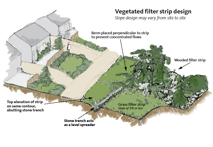
Ideal slopes in the direction of flow across the facility are 5 percent or less; slopes of up to 15 percent are acceptable but not encouraged (Arnold 1993, Field 2007). Steeper slopes do not allow time for infiltration and pollutant removal, but different vegetation types can aid in infiltration, affecting the slope suitable for a specific site. Steeper slopes generally require larger facilities; the slope in the direction perpendicular to the flow should not exceed 2 percent. To slow the speed of the water, consider the slope of the impervious area draining to the VFS, which should be no more 2 percent in the direction of the flow across the pavement or more than 4 percent in the direction of flow perpendicular to the pavement.
Flow velocities
VFSs are not designed to handle high velocities of runoff (Field 2007). Overland flow and spreader facilities help to keep the velocities below erosive levels, but this should be confirmed in the design. Dense plantings will also play a significant role in slowing flows and aiding infiltration.
Soils and media
Vegetated filter strips may be installed on native soils, amended native soils, or amended planting soil mixes with infiltration rates that allow for stormwater to pass through the soil column for treatment. Infiltration rates should not be so high that stormwater doesn’t have enough “retention time” in the soil; the ideal infiltration rate is between ½ inch per hour and 12 inches per hour. The top 18 inches of soil is typically amended with organic compost. In some cases, existing topsoil is replaced with a soil mix, as specified by the local jurisdiction. Overly sandy mixes can increase irrigation needs and and the odds of having to replace the plants. Ensure that any imported soil and compost are free of weed seeds. Other key considerations for robust plant establishment and stormwater treatment include a soil pH between 5.5 and 7.5 and a cation-exchange capacity greater than 5 millequivalents/100 grams (LIDC 2003).
Replacing native soil with amended soil may trigger state underground injection control (UIC) requirements, depending on the VFS design (see Permits, page 5).
Test soil in the proposed filter strip location to determine the infiltration rate of the native undisturbed soils below the amended topsoil. For stand-alone facilities, the infiltration rate should be at least 2 inches per hour, since a VFS is a flow-based facility with no capacity for ponding water to infiltrate at a later time. The infiltration rate can be extremely low if the VFS is being used for pretreatment only. There is no recommended maximum infiltration rate for native soils.
Vegetation
The interaction of soil, plants, and the beneficial microbes that concentrate on plant roots is what ultimately provides the filtration benefit of a VFS—the more plants, the better the treatment. A vegetated filter strip that won’t infiltrate the water-quality storm (the small, frequent storm event) will still provide some reduction of total suspended solids. Plant density is even more important in this case, since the above-ground structure of the plants is what slows runoff and allows sediments to settle out; choose plants able to withstand the flow of water without drooping over.
Several varieties of trees, shrubs, grasses, and ground covers may be planted in filter strips in both sun and shade conditions. Plant densely to maximize runoff treatment and control weeds; dense vegetation also reduces maintenance. Local jurisdictions often provide specifications for density, size, and types of vegetation to use. Choose plants based on their tolerance to flooding and their ability to survive in local climate conditions without the use of fertilizers, herbicides, or insecticides. Plants should need minimal to no watering after establishment. Perennial flowers, ornamental grasses, and shrubs can add significant appeal. Filter strips can also be designed to attract beneficial insects and wildlife. Contact your local OSU Extension Service office or planning department for a list of plants appropriate for your area.
Avoid noxious weeds and invasive plants. Seeds of these plants have been known to travel downstream to natural wetlands during flooding and are sometimes spread by birds. Check the list of noxious weeds on the Oregon Department of Agriculture’s website at www.oregon.gov/oda/programs/weeds/pages/aboutweeds.aspx.
When possible, choose native plants. Nonnative seeds and rhizomes can negatively affect the habitat potential and hydrology of our natural waterways. Native plants support native microbes and other soil life and are a better food source for native insects and birds. If your jurisdiction does not have plant recommendations, contact the local soil and conservation district or visit the USDA PLANTS database (plants.usda.gov) and use the advanced search option to generate your own list. The Washington Department of Ecology provides an extensive list of plants adapted for climates east of the Cascades (WDOE, 2013).
In cold climates, VFSs and other bioretention facilities may be used to store snow or to treat runoff from an area that was treated with salt as a deicer. In these circumstances, select salt-tolerant, nonwoody species (EPA, 2013.)
Routing
The flow of runoff entering a VFS should not be a concentrated stream, but spread out to help prevent erosion. Use a level spreader to accomplish this function.
A level spreader is a stone-filled gravel trench, with or without a perforated pipe, concrete weir, runnel, or curb (Arnold 1993). In designing a level spreader and other VFS components, take care to avoid triggering UIC requirements (see Permits, below). Regardless of type, the spreader should be continuous and level (See Barr 2001, Field 2007). As an alternative, place dams or berms at the top of the facility every 50 to 100 feet (Arnold 1993).
As is the case with many low-impact development facilities, a bypass system may be needed for high flows during storms that exceed the design capacity (Barr 2001). A berm at the bottom of the facility will allow ponding, but the effectiveness of this measure depends on the slope of the facility and the height of the berm. Other bypass systems include an underdrain and overflow weir (Field 2007).
Construction
As in all stormwater facilities, construction details are critical. If a facility will be used for infiltration, fence off the site to prevent vehicle and foot traffic that can compact soils and reduce the infiltration rate. To protect soils during excavation, use track equipment or excavate from the sides of the infiltration area. If the soils are exposed to rain, fine soil particles could clog the native subgrade soils. On a dry day, rake the surface to a depth of 3 inches to loosen soil before proceeding, or fold a few inches of compost into 8 to 12 inches of soil using a garden spade. Compost amendment will also be needed if the vegetated filter strip is located in clayey soil and is dug by hand because foot traffic in the area is probably unavoidable.
If the facility is for filtration only, protection from compaction isn’t as critical. But any infiltration that can be achieved would be beneficial as long as appropriate setbacks are in effect. Note that vegetation is difficult to establish in compacted soils, so it’s still wise to take preventive measures.
Maintenance
Because vegetated filter strips can resemble regular gardens, consider some sort of permanent demarcation to prevent long-term compaction, particularly in residential areas where owner turnover rates tend to be high compared to other uses of land.
Common maintenance tasks:
- Mow and trim dry grasses.
- Replace plants as needed.
- Repair eroded areas where channels have formed.
- Maintain the level spreader.
- Inspect for excess sediment that may affect plant growth.
- Check for sediment in pretreatment facilities such as sumped catch basins. Dispose of any sediments in an approved location; check with the local jurisdiction (Barr 2001).
Consistent maintenance ensures longevity and effectiveness of the facility, and VFSs require less maintenance than other vegetated best-management practices (LIDMM 2008).
Permits
Consult your local planning and building department. Ask about applicable permits, plumbing codes, and piping requirements. Find out if there are any maps, as-built drawings, or site-specific constraints. In many cases, a commercial building permit will be required, and a clearing, grading, and erosion control permit may be required if ground disturbance is extensive.
UIC regulations
A Class V Underground Injection Control is a system designed for the subsurface placement of fluids and is regulated through the Oregon Department of Environmental Quality’s (ODEQ) UIC program. This program protects groundwater resources from injection of pollutants directly underground.
According to the U.S. Environmental Protection Agency, a Class V UIC well is:
- Any bored, drilled or driven shaft; or
- A dug hole whose depth is greater than its largest surface dimension; or
- An improved sinkhole; or
- A subsurface fluid distribution system (an assemblage of perforated pipes or drain tiles used to distribute fluids below the surface of the ground).”
UIC regulations would be triggered in the rare case that a perforated pipe is used either in an unlined spreader trench or as an underdrain below the facility. To avoid triggering UIC regulations when sizing a VFS, make sure your facility is wider than it is deep.
If a VFS is being considered for pretreating runoff before discharging it to a UIC, such as a drywell or soakage trench, contact ODEQ’s UIC Program during early design stages for information about the approval process and how to expedite it. For more information on low-impact development and UICs, see ODEQ’s fact sheet, “Identifying an Underground Injection Control” (ODEQ 2015).
References and resources
Arnold, J. A. (ed.), D. E. Line, S. W. Coffey, and J. Spooner. 1993. Stormwater Management Guidance Manual. Raleigh, NC: North Carolina Cooperative Extension Service and North Carolina Division of Environmental Management.
Barr Engineering Company. 2001. Minnesota Urban Small Sites BMP Manual: Stormwater Best Management Practices for Cold Climates. St. Paul, MN: Metropolitan Council Environmental Services.
Center for Watershed Protection (CWP) and Chesapeake Stormwater Network (CSN). 2008. Technical Memorandum: The Runoff Reduction Method. Ellicott City, MD.
City of Portland, Bureau of Environmental Services. 2016. Portland Stormwater Management Manual (PSMM). Portland, OR.
Field, R., T. N. Tafuri, S. Muthukrishnan, R. A. Acquisto, and A. Selvakumar. 2006. The Use of Best Management Practices (BMPs) in Urban Watersheds. Lancaster, PA: DEStech Publications, Inc.
Lower Columbia River Estuary Partnership. Lower Columbia River Field Guide to Water Quality Friendly Development: Techniques and Examples. Accessed from: http://www.lcrep.org/sites/default/files/fieldguide/techniques.htm
Southeast Michigan Council of Governments. 2008. Low Impact Development Manual for Michigan (LIDMM): A design guide for implementers and reviewers.
North Carolina Division of Water Quality. July 2007. Stormwater Best Management Practices Manual. Raleigh, NC.
Oregon Department of Environmental Quality. 2015. Fact Sheet: Identifying an Underground Injection Control. Portland, OR. Accessed from www.oregon.gov/deq/FilterDocs/IDswInjSysFS.pdf
The Retardation of Heavy Metals in Stormwater Runoff by Highway Grass Strips: http://www.wsdot.wa.gov/research/reports/fullreports/404.1.pdf
Urban Drainage and Flood Control District (UDFCD). 1999 (rev. 2008). Drainage Criteria Manual (Vol 3). Denver, CO. http://udfcd.org/criteria-manual
Washington Department of Ecology, 2013. Eastern Washington Low Impact Development Guidance Manual. Pub no. 13-10-036. https://fortress.wa.gov/ecy/publications/SummaryPages/1310036.html
Table 1. Peak flows from 10,000 square feet of runoff
|
Storm type |
Peak flow (cfs*) |
|
Type IA |
0.11 |
|
Type I |
0.33 |
|
Type II |
0.65 |
*Cubic feet per second
© 2018 Oregon State University.
Extension work is a cooperative program of Oregon State University, the U.S. Department of Agriculture, and Oregon counties. Oregon State University Extension Service offers educational programs, activities, and materials without discrimination on the basis of race, color, national origin, religion, sex, gender identity (including gender expression), sexual orientation, disability, age, marital status, familial/parental status, income derived from a public assistance program, political beliefs, genetic information, veteran’s status, reprisal or retaliation for prior civil rights activity. (Not all prohibited bases apply to all programs.) Oregon State University Extension Service is an AA/EOE/Veterans/Disabled.
About the authors