Soakage trenches are a space-saving way to manage runoff and preserve aesthetics at a site, but they are costly to build and maintain.
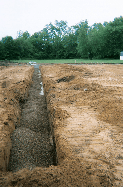
Soakage trenches, also known as infiltration trenches or recharge beds, are excavated trenches wrapped in filter fabric and filled with coarse stone. Soakage trenches receive runoff via pipes and store it in the rock voids until it is able to infiltrate, or seep, into surrounding soils. The U.S. Environmental Protection Agency (EPA) defines soakage trenches as assemblages of perforated pipes, drain tiles, or similar mechanisms designed to distribute fluids below the surface of the ground.
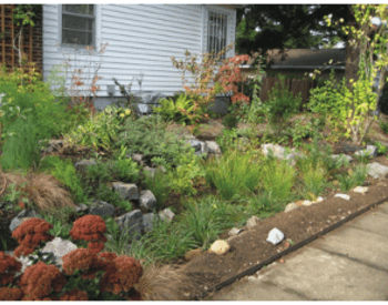
The soil placed above the assembly can be planted with lawn, groundcover, or shrubs or covered with pavement or rock to look like a dry creek bed.
Soakage trenches may fall under the Oregon Department of Environmental Control’s (ODEQ) underground injection control (UIC) rules if the infiltration occurs via a perforated pipe.
Site conditions
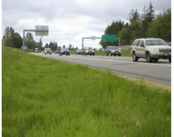
Soakage trenches occupy less space than many other best management practices (Field et al. 2007), and the space they occupy is often available for another use at the surface. Potential locations include front, side, and back yards. They are suitable for both public and private property, and even rights-of-way. Soakage trenches may be built in new and existing developments or used as retrofits. Although they are generally designed for smaller areas, trenches can be constructed to help manage the appropriate volume of runoff.
Good sites for a soakage trench
- On land slopes of less than a 10 percent grade;
- Where the bedrock or other impermeable layer is at least 24 inches from the bottom of the soakage trench;
- At least 100 feet uphill of a steep slope (preferably at the bottom of a hill); and,
- In any location approved by a qualified licensed engineer or geologist who has signed and stamped a geotechnical report, site plan, or letter clearly designating the location.
Check with your local jurisdiction for proper siting criteria.
Poor sites for a soakage trench
- Where the seasonal high groundwater table is close than 24 inches from the bottom of the trench. These are not rule-authorized by ODEQ (see UIC Regulatory Approval) ;
- Where bedrock or other impermeable material is closer than 18 inches from the bottom of the soakage trench;
- In contaminated soils;
- On slopes exceeding 10 percent;
- Under the canopy of existing trees;
- Where adequate setbacks discussed previously cannot be met;
- Where soils are unstable (NCDWQ 2007, Field et al. 2007);
- Over karst bedrock (landscape underlain by eroded limestone) (NCDWQ 2007, Field et al. 2007);
- Where hazardous or toxic materials are stored, transported, or otherwise handled; or
- Where an accidental spill of a hazardous or toxic liquid would drain into the facility.
Prohibited sites
The following restrictions apply to soakage trenches that ODEQ authorizes by rule:
- Within 500 feet of a water supply well
- Within the two-year time of travel for a public supply well
- At an intersection with the groundwater table. ODEQ recommends that soakage trenches have at least 5 feet of vertical separation from the seasonal high groundwater table.
Removing pollutants
While a literature search for information on the pollutant removal capacity of soakage trenches will yield results, ODEQ strictly regulates all UICs and may require adequate pretreatment before disposal is permitted.
Cost
Construction costs range from medium to high (NCDWQ 2007). Because these facilities can be easily installed in small spaces, they are often cost-effective to build (Arnold 1993). However, a clogged facility cannot be unclogged without excavating the entire system and replacing it, which would contribute to the lifetime cost of the system (ASCE 2001).
Soakage trenches with perforated pipes cost more because:
- Systems with perforated pipes located at the bottom of the rock that are also connected to a nonperforated large storm overflow pipe require a control structure, such as a concrete catch basin with a weir, to ensure that water backs up into the rock and is stored for infiltration. Developers will have to order a custom catch basin and pay for delivery.
- Costs to register as UICs through the ODEQ vary from $300 to $1,002, and the cost of preparing the required permitting documentation can be as high as $2,000.
- Spill response materials must be kept on site, and personnel must be trained in spill response measures.
One more factor affecting the bottom line: the potential cost of retrofitting existing soakage trenches to meet the requirements of any future regulations enacted to protect Oregon’s groundwater resources. There are no grandfathering provisions in place for soakage trenches (ODEQ 2010a).
Design
Soakage trenches are typically designed to capture the stormwater runoff during 80–95 percent of annual storm events, on average. Runoff is stored in the voids between the course stone, which should be specified as “open-graded,” or crushed aggregate that is all of the same or similar diameter. Concentrated runoff may be directed via a perforated pipe installed along the centerline of the soakage trench.
Runoff may also flow in a shallow sheet over a surface to a soakage trench located at grade. In this case, a perforated pipe may not be needed, and the system would not be considered a UIC as long as the soakage trench is wider than it is deep. Check with your local planning department for specific design requirements for your area.
Pretreatment facilities settle sediments and particulates before the runoff enters the facility. For UIC facilities, the DEQ requires pretreatment of the runoff from roads and parking areas prior to entering the trench. Due to accessibility difficulties, these are also more expensive to maintain (Field et al. 2007).
Pretreatment is also recommended for soakage trenches that are not designated UICs.
If soakage trenches are installed beneath impervious pavement, the pavement section in that area must be designed and installed in a fashion similar to that of porous pavements (see the Porous Pavement fact sheet in this series). In addition, you may need a deeper layer of rock to ensure adequate structural stability, due to the lower levels of compaction that porous pavements receive. The rock itself should be lightly compacted.
Regardless of the final contours of the soil above a soakage trench, take care to prevent native soils at the bottom from becoming compacted.
Sizing
As a general guideline, soakage trenches should not manage runoff from drainage areas greater than 5 acres (Arnold 1993, NCDWQ 2007), and less than 2 acres is preferred (Barr 2001, SEMCOG 2008). In theory, they should manage much smaller areas.
A well-designed, low-impact development project should incorporate small, numerous facilities that are well distributed both in the uphill and downhill areas of a given site or watershed. A general rule is that infiltration facilities that manage runoff should receive no more than 10,000–15,000 square feet of impervious drainage area, or the equivalent in landscape area (approximately 11,750–17,500 square feet).
The design of soakage trenches across the state depends on the volume of rainfall anticipated in each region.
Stormwater managers set standards for system capacity by measuring the intensity of precipitation over a period of time. A “design” storm is a theoretical storm that facilities such as soakage trenches are designed to treat. The size of the storm is analyzed to occur at a given frequency. They are described as 6-month, 1-year, 2-year, 25-year or 100-year storms that occur over a 6-hour or 24-hour period. The size and duration of the design storm is typically specified by local regulations. Check the Soil Conservation Service Storm Type map at http://extension.oregonstate.edu/stormwater/what-storm-type-do-you-live.
A rainfall distribution is a statistical representation of the intensity and duration of rainfall that occurs on average for each storm. These distributions provide a way to model the intensity and duration of rainfall for a given design storm. Oregon has three different rainfall distributions, called Type IA, Type I, and Type II. Type IA is a lower intensity, longer duration storm typical of western Oregon, while Type II storms are higher intensity, shorter duration storms. Type I storms fall in between these two. Each jurisdiction will develop its own requirements for the size of storm (design storm) and distribution type (1A, 1 and II) based on goals for water quality and quantity.
Soakage trenches are designed to infiltrate within 30 hours to be available for the next storm for a Type IA storm distribution, and within 72 hours for Type I and Type II storm distributions. They should only overflow during events larger then the design storm.
This ensures that the trench will be empty and ready for the next storm. In situations where surfaces are impervious and essentially all rainfall becomes runoff (for example, rooftops, driveways, sidewalks, and areas of fill, even if landscaped), the footprint of the soakage trench typically ranges from 4 to 12 percent of the impervious surfaces draining to it (Table 1). Slower infiltration rates (the rate at which water soaks into the soil) will make the facility footprints larger; however, most jurisdictions have no need to infiltrate the 25-year storm, so if the design storm is smaller, then expect the final design footprint to be smaller than the facility footprints in the table.
Facility area will vary with site conditions and is dependent on factors such as soil type, the volume of water to be treated, the depth to groundwater, and the void percentage of the washed storage rock (usually 40 percent). The amount of runoff routed to the infiltration trench depends on local rainfall patterns, the area of surfaces draining to the garden, and how much of the water runs off these surfaces. Impervious surfaces will generate the most runoff; simple landscapes such as lawns will generate a moderate amount of runoff; and complex garden areas with trees, shrubs, and mulch will generate the least, if any, runoff.
Soakage trenches should be designed wide and shallow rather than deep and narrow. A side-to-bottom ratio of 1:4 is recommended (Arnold 1993), with a rectangular cross-section (Field et al. 2007). The width at the bottom should be 2–25 feet, constructed perpendicular to flow direction (NCDWQ 2007, NRCS 2008).
For soakage trenches that are designed underneath either porous or impervious pavements, the width might exceed 25 feet, and the area is often equal to a convenient area of pavement based on existing contours. Designing the trenches into the existing contours will reduce excavation and allow for the maximum effective storage volume as water infiltrates. Soakage trenches running perpendicular to contours should be designed so that they don’t direct water to undesirable locations. Instead, step them down the hill by creating underground berms between beds. Excess runoff cascades over berm after berm, to be captured by an overflow pipe with a control structure and carried downstream. As with all infiltration facilities, a larger footprint will result in more effective infiltration capacity, and less storage (in this case, depth of rock) will be needed to infiltrate runoff. More information about this approach can be found in the publication, Porous Asphalt Pavement with Recharge Beds, 20 Years and Still Working (Adams 2003).
Several design and sizing equations are available in both Barr (2001) and NCDWQ (2007). Alternatively, developers can use soakage trench sizing calculators.
Design is critical to the durability and longevity of soakage trenches. Perform field tests of soil infiltration rates and investigate for impermeable layers, rather than trying to determine construction location from preexisting data (Field et al. 2007).
Slope
A grade at the bottom of the facility of between 0.0 percent and 0.5 percent is appropriate (NCDWQ 2007). Slopes at the ground surface above the facility may exceed 0.5 percent without impacting functionality, since the soakage trench is an independent assembly buried below the surface. If slopes on the bottom of the facility exceed 0.5 percent, a soakage trench on its own can be stepped down the hill.
Soils and medium
Like all infiltration facilities, soakage trenches should be installed in soils that infiltrate. Perform infiltration tests to ensure an adequately sized facility (Barr 2001). See Infiltration Testing, EM 9214.
Pretreated runoff directed to these systems has no maximum infiltration rate; however, if pretreatment is not provided, the soil receiving runoff should drain no faster than 12 inches per hour to ensure adequate retention time in the soil to decrease pollutant levels before water mixes with groundwater.
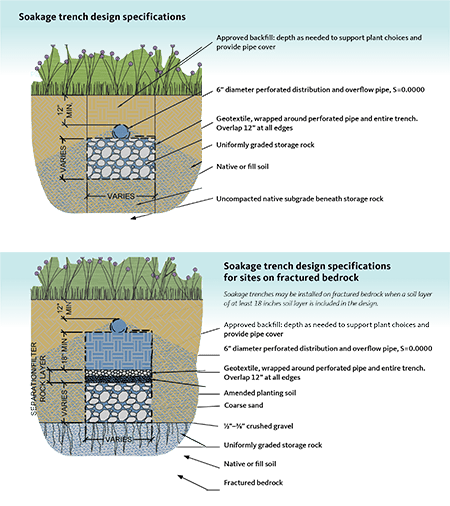
Storage rock
The storage rock medium is a uniformly graded
aggregate with about 40 percent pore space (Arnold 1993, Barr 2001, Field et al. 2007). It should be crushed, washed, uniform, and durable, and should contain no fine material such as slate, shale, clay, silt, or other organic matter (NCDWQ 2007).
It’s okay to substitute concrete or plastic vaults with open bottoms (NCDWQ 2007) in place of the uniformly graded aggregate. These chambers work best in areas with high water tables or impermeable layers, where the soakage trench needs to be shallow enough to to provide adequate separation (as described in “Site Conditions” above) with these barriers (BES 2008).
Vegetation
Since runoff does not pass through a ground surface but instead is delivered directly underground via a pipe, vegetation does not play a direct role in improving water quality.
The soil over soakage trenches dries out faster than other soils, so any plants should be hardy ones. A rule of thumb for grass is that its roots will grow as deep as the plant is allowed to grow tall. Deep-rooting plants can ruin piping systems (LCREP 2006, Arnold 1993). If plans call for larger plants and conditions allow for a deeper soakage trench, add more soil to accommodate the roots of shrubs (at a minimum soil depth of 24 inches) and trees (36 inches).
While trees are not recommended for soakage trenches with perforated pipes, it’s okay to plant them over soakage trenches where there is no piping.
Filter fabric
The sides, bottom and top of the trench should be lined with geotextile, or filter fabric. This design provides separation between the soil and trench rock and can prevent clogging (Field et al. 2007, Barr 2001). Filter fabric segments should overlap by 12 inches, a layering pattern referred to as the “shingle effect” (Field et al. 2007). Since geotextiles tend to clog if the rock isn’t clean enough when installed, the bottom layer of filter fabric can be replaced with a 6- to 12-inch layer of clean sand as an alternative (Field et al. 2007).
Observation wells
An observation well is vertical piping that provides a means of visually observing that the facility is infiltrating, which is especially important for facilities with overflow pipes. If a soakage trench stops infiltrating, then the observation well will always be full and subsequent runoff will simply bypass the system, with no management of water quantity or flow whatsoever.
Place at least one observation well near the center of the soakage trench; guidelines suggest more wells at every 50 feet. Use PVC pipes 4–6 inches in diameter, properly attached to the base of the trench and capped above ground. (Field et al. 2007, Barr 2001, NCDWQ 2007).
Routing
A perforated pipe embedded in the trench is usually used to distribute runoff across the length of the trench, but a level spreader uphill of the trench may also be used.
To reduce the volume of suspended solids entering the trench, regulations require the use of pretreatment facilities such as filter strips, grit chambers, grassed swales, silt basins, or forebays (NCDWQ 2007, Field et al. 2007). Rain gardens and proprietary filters also serve to remove sediments and soils (Field et al. 2007)—and may be required depending on ODEQ permitting. Since soakage trenches are prone to clogging, difficult to maintain, and expensive to replace, a facility with higher potential to pollute requires greater care in the design and function of the pretreatment device (Field et al. 2007). While ODEQ doesn’t require pretreatment of roof runoff, consider a silt basin that reduces sediment to protect the system against long-term clogging. Fine sediments and other pollutants can be deposited by air and will increase the likelihood of premature clogging and replacement. In addition, roofs may introduce a number of soluble pollutants (such as biological contaminants or hydrocarbons from asphalt shingles) that warrant additional treatment in sensitive areas. Runoff from traffic areas must be treated more robustly.
Overflow systems ensure that large storms don’t back up and flow out from the system too close to buildings. Even when the system is designed to infiltrate all of the stormwater, there will always be a larger storm that will overwhelm the system. Perforated pipes can be placed at the bottom of the facility, where they will collect runoff. These will decrease infiltration potential by piping water off the site before it is able to soak into soils. In this case use a control structure, located at the lowest, overflow elevation of the soakage trench, to back up into the voids and infiltrate. This increases upfront construction and long-term maintenance expenses but is sometimes necessary to achieve adequate depth of soil to protect the structural integrity of the pipe.
Ideally, a perforated spreader pipe at the top of the facility can double as the underdrain and overflow pipe and will capture runoff only when it reaches this higher elevation (ASCE 2001, Field et al. 2007). Check local plumbing and piping codes for sizing and discrepancies between public and private facilities (BES 2008).
Construction
As with all stormwater management facilities, take care to properly construct a soakage trench. Fence off the proposed trench location to prevent car and foot traffic that could compact soils. Use plastic orange protection fencing or rented chain link, and post signs. The general contractor should hold a preconstruction meeting with all subcontractors explaining their roles and responsibilities in protecting water quality. Use low-compaction construction techniques, such as track equipment or excavating from the sides of the infiltration area, to protect the soils during excavation (Barr 2001, NCDWQ 2007, BES 2008). If the soils are exposed to rain, fine soil particles will be picked up and moved around and may clog the native subgrade soils. On a dry day, rake the surface to a depth of 3 inches or amend the soils by folding in a few inches of compost into the bottom 8 to 12 inches of the soakage trench before proceeding. Compost will also be needed if the soakage trench is dug by hand, because foot traffic in the facility area might be unavoidable.
Maintenance
While proper design has a big influence on how long and how well a soakage trench functions, careful maintenance to prevent clogging will have the greatest impact. Maintenance demands range from medium to high, and, in some cases these demands are considered to be a limitation (Arnold 1993, Barr 2001, NCDWQ 2007). Inspect the facility every three months and after large storms for the first year, and then once per year and after major storms (Barr 2001, NCDWQ 2007). Maintenance schedules for pretreatment vary depending on the approach. See the fact sheets on Rain Gardens, Vegetated Filter Strips, and Planters in this series. For structures such as silt basins and water-quality manholes, follow the manufacturer’s guidelines.
Maintenance tasks:
- Examine soakage trench for erosion at the overflow location and sediment buildup in the pretreatment structure or facility.
- Observe infiltration rates to look for slowing (i.e., water takes longer and longer to drop in the observation well(s)).
- Remove sediment and debris from the pretreatment structure or facility.
- Protect and repair structures such as pretreatment and control structures, inspection ports, and cleanouts) (Arnold 1993, Barr 2001, LCREP 2006, NCDWQ 2007).
Sediment and debris tend to clog the surface of soakage trenches that receive runoff from adjacent surfaces. Sediment must then be vacuumed from the rocks. If water can no longer drain into the facility, that means the top layer of filter fabric is clogged. Using sediment control techniques such as compost berms and biobags, remove and clean rock on the surface. Replace the filter fabric on the top, being careful not to damage the fabric on the sides. Place the cleaned rock back over the new layer of fabric. Dispose of sediment in trash destined for the landfill.
Sweeping regularly will reduce the likelihood of clogging. High-traffic areas will clog faster than low-traffic areas. When properly maintained, these facilities can last up to 30 years (LCREP 2006), although ODEQ’s UIC stormwater management guidelines indicate that they often fail within five years.
Permits
Consult your local planning and building department. Ask about applicable permits, plumbing codes, and piping requirements. Find out if there are any maps, as-built drawings, or site-specific constraints. In many cases, a commercial building permit is required to build a soakage trench on a nonresidential site. A clearing, grading, and erosion-control permit may be required if the area of ground disturbance is large enough.
UIC Regulatory Approval
Soakage trenches with perforated pipes are regulated under ODEQ’s Class V UIC program. This program protects groundwater resources from injection of pollutants directly underground and may require a more formal permitting process, depending on the potential for pollution.
According to the U.S. Environmental Protection Agency, a Class V UIC well is:
- Any bored, drilled or driven shaft; or
- A dug hole whose depth is greater than its largest surface dimension; or
- An improved sinkhole; or
- A subsurface fluid distribution system (an assemblage of perforated pipes or drain tiles used to distribute fluids below the surface of the ground).
These systems are regulated throughout the state because, unlike rain gardens and swales, they don’t inherently remove pollutants, so are much more likely to pollute groundwater.
Soakage trenches without perforated pipes that receive runoff through the top surface area are not considered UICs.
The following requirements apply to soakage trenches with perforated pipes only:
- A long-term stormwater management plan that includes a description of the best management practices for the entire site;
- Spill prevention and response;
- A maintenance plan and schedule;
- And an employee training record.
The plan must be revisited every five years or immediately after a spill, and the facility itself must then be repermitted. The ODEQ has very specific guidelines for pretreatment and other permitting requirements that you can find on its website (ODEQ 2018).
Note that state rules prohibit the use of injection systems where better treatment or protection is an option, such as when a stormwater or municipal sewer is available. These services are considered available if the system is not at capacity or is within 300 feet of the site. (ODEQ 2010b). Facilities also fall under the requirements of the state Groundwater Quality Protection Act.
There may be alternatives to the use of soakage trenches and other UICs. If site constraints allow, consider other surface-infiltrating low-impact development techniques, such as rain gardens, planters, swales, vegetated filter strips, porous pavement, and green roofs. (Refer to the other fact sheets in this series.) Other nonstructural techniques, such as better site design, will help reduce runoff. Some examples of better site design include natural-area conservation, open space or cluster design, reduced street widths, reduced sidewalks, shorter driveways, and impervious surface disconnection.
Most UICs fall under the category of state rule authorization, not permitting. Individual residential roof soakage trenches are not required to register and receive ODEQ approval as UICs, unless the city requests the review due to high groundwater concerns. Fourplexes, apartment houses, and commercial and industrial roof drains do need ODEQ approval though rule authorization. Usually no pretreatment is required as long as the discharge is just roof runoff. If the trench drain serves a parking area, driveway, garbage bin, or loading dock, however, it must be registered and approved by ODEQ. Trenches with a depth dimension less than their largest surface dimension and no perforated pipe are not categorized as injection wells (NCDWQ 2007).
Note that cities and counties cannot approve UICs; only ODEQ has this authority. For more information, visit the DEQ website (ODEQ 2018).
References and resources
Adams, Michele C. 2003. Porous Asphalt Pavement with Recharge Beds, 20 Years and Still Working. In Stormwater: May–June 2003. Accessed from http://www.biaw.com/documents/LID/BMPS/porous_asphalt_pavement.pdf
American Society of Civil Engineers (ASCE), Environmental and Water Resources Institute. 2001. Guide for Best Management Practice (BMP) Selection in Urban Developed Areas. Produced by Urban Water Infrastructure Management Committee’s Task Committee for Evaluating Best Management Practices.
Arnold, J. A. (ed.), D. E. Line, S. W. Coffey, and J. Spooner. 1993. Stormwater Management Guidance Manual. North Carolina Cooperative Extension Service and North Carolina Division of Environmental Management. Raleigh, NC.
Barr Engineering Company. 2001. Minnesota Urban Small Sites BMP Manual: Stormwater Best Management Practices for Cold Climates. Metropolitan Council Environmental Services, St. Paul, MN. Accessed from http://www.metrocouncil.org/environment/Water/BMP/manual.htm
Bureau of Environmental Services (BES). 2008. Portland Stormwater Management Manual. City of Portland, Portland, OR. Accessed from http://www.portlandonline.com/bes/index.cfm?c=47952
Center for Watershed Protection (CWP) and Chesapeake Stormwater Network (CSN). 2008. Technical Memorandum: The Runoff Reduction Method. Ellicott City, MD.
Field, R., T. N. Tafuri, S. Muthukrishnan, R. A. Acquisto, and A. Selvakumar. 2006. The Use of Best Management Practices (BMPs) in Urban Watersheds. DEStech Publications, Inc., Lancaster, PA.
Lower Columbia River Estuary Partnership (LCREP). 2006. Lower Columbia River Field Guide to Water Fuality Friendly Development. Prepared by City of Portland Bureau of Environmental Services. Accessed from http://www.lcrep.org/sites/default/files/fieldguide
North Carolina Division of Water Quality (NCDWQ). 2007. Stormwater Best Management Practices Manual. Raleigh, NC.
Oregon Department of Environmental Quality (ODEQ). 2018. DEQ Stormwater Management Guidelines. UIC Fact Sheets and Guidance. Portland, OR. Accessed from http://www.oregon.gov/deq/wq/wqpermits/Pages/UIC-Guidance.aspx
Natural Resources Conservation Service (NRCS). 2010. Urban BMPs—Water Runoff Management. In NRCS Planning and Design Manual. Accessed from http://www.wsi.nrcs.usda.gov/products/UrbanBMPs/water.html
Southeast Michigan Council of Governments (SEMCOG). 2008. Low Impact Development Manual for Michigan: A design guide for implementers and reviewers. Detroit, MI.
Urban Drainage and Flood Control District (UDFCD). 1999, rev. 2008. Drainage Criteria Manual (Vol 3). Denver, CO.
Minimum setbacks
- 5 feet from property lines (although they are allowed to be situated on the right-of-way line)
- 10 feet from building foundations
- 20 feet, if a structure is located downslope
- 100 feet, if located upslope of steep slopes (BES 2008). (However, locating a soakage trench at the bottom of a hill is the preferred option.)
- 30 feet from surface waters
- 500 feet from water supply wells and drinking water springs (ODEQ 1998)
- 100 feet from septic tanks or drain fields
- 20 feet from riparian buffers or growth protection easements
- 50 feet from the top of slopes greater than 15 percent (Barr 2001, LCREP 2006, Field 2007, BES 2008, NCDWQ 2007)
Peak flow comparison and sizing examples
Modeling results to infiltrate runoff from 10,000 square feet of impervious area at a rate of 2 inches/hour during a 25-year, 24-hour design storm
|
|
25-year event depth (inches) |
Distribution |
Peak flow in cubic feet per second (cfs) |
Soakage trench footprint needed (square feet) |
Percentage of facility size compared to impervious drainage area |
Peak flow exceeding soakage trench storage (cfs) |
Maximum ponding depth in planter (inches) |
|
Salem |
4 |
Type IA |
0.22 |
856 |
8.6% |
0 |
23.9 |
|
Coos Bay |
5.5 |
Type IA |
0.30 |
1,184 |
11.8% |
0 |
24.0 |
|
Redmond |
1.8 |
Type I |
0.29 |
432 |
4.3% |
0 |
24.0 |
|
Wasco |
2.3 |
Type I |
0.38 |
624 |
6.2% |
0 |
24.0 |
|
La Grande |
2.4 |
Type II |
0.78 |
936 |
9.4% |
0 |
23.9 |
|
Pendleton |
1.6 |
Type II |
0.51 |
600 |
6.0% |
0 |
24.0 |
© 2018 Oregon State University.
Extension work is a cooperative program of Oregon State University, the U.S. Department of Agriculture, and Oregon counties. Oregon State University Extension Service offers educational programs, activities, and materials without discrimination on the basis of race, color, national origin, religion, sex, gender identity (including gender expression), sexual orientation, disability, age, marital status, familial/parental status, income derived from a public assistance program, political beliefs, genetic information, veteran’s status, reprisal or retaliation for prior civil rights activity. (Not all prohibited bases apply to all programs.) Oregon State University Extension Service is an AA/EOE/Veterans/Disabled.
About the authors