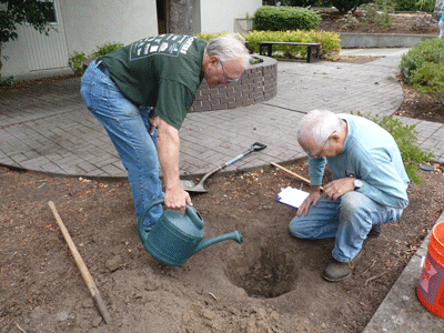
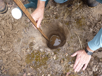
One of the first steps in siting a low-impact development facility is infiltration testing. Infiltration tests estimate the rate at which runoff will infiltrate, or pass through, native soil. An infiltration test, in essence, involves digging a hole, pouring in water, and measuring the drop in water level over time.
This information is used to answer three important questions:
- Is the site suitable for an infiltration facility?
- Can the site be developed to meet water quality standards?
- What size of low-impact development (LID) facility should be installed?
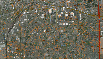
Existing soil or geologic maps can be used in the initial steps to evaluate the site’s potential for infiltration, but maps alone don’t present enough information. Infiltration testing often reveals different conditions at different places on the site and at different depths.
Tests can vary by the size of area contributing runoff to the LID facility and the type of facility (PSAT 2005). These infiltration facilities include infiltration rain gardens, vegetated filter strips, porous pavements, infiltration planters, swales, drywells, and soakage trenches.
In contrast, filtration facilities, such as filtration rain gardens and planters designed to slow the flow of water rather than treat runoff, allow the runoff to pass through only the upper layers of soil to an underground perforated pipe, which routes the water offsite. Those constructing filtration facilities don’t need to test native soils, but the amended soil should be tested to ensure that the facility can convey the appropriate volume of water.
When and where
There are certain times when an infiltration test should wait: Do not test during a rainstorm, within 24 hours of a significant (greater than ½ inch) rainstorm, or when the ground is frozen (LIDMM 2008).
The tests proposed here measure infiltration of small, specific areas. If the proposed facility encompasses a large area, take multiple measurements within the area to properly assess the site’s suitability (PSAT 2005).
Infiltration tests should be performed across the proposed development area prior to full build-out. This provides the opportunity to install LID facilities on optimal soils and geology. If buildings are proposed on slower infiltrating soils and stormwater facilities proposed in faster infiltrating soils, builders can plan their sites to improve stormwater management, prevent flooding, address water-quality issues, and decrease the cost of the on-site stormwater management facilities. The earlier in the development process infiltration tests are conducted, the better. Infiltration information will ultimately be necessary to select and design LID facilities.
Testing depth
It’s a good idea to conduct infiltration testing at the same depth as the bottom of the LID facility you expect to install. But in many cases, the test itself determines how deep the facility should extend as well as its location. How, then, should you proceed?
Some guidelines:
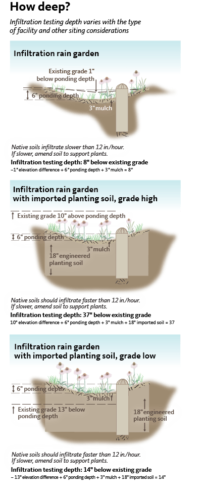
- Test at shallow depths. Soils just 6 inches below existing grade may be suitable for infiltration and have enough nutrients to support plant growth. In these cases, consider a simple facility that doesn’t replace the native soils.
- Test at multiple depths.
- Compare existing surface elevation to design elevation to help determine appropriate testing depths.
Deep drywells, where the bottom and sides of the facility would be too costly to access safely, pose a special challenge for infiltration testing. Because drywells are vertical in nature, they are more likely to pass through two or more different soil horizons. Often, drywells are chosen because infiltration rates are poor at the surface of the soil or because site surface area is limited. Sometimes a better-draining soil exists some feet below the surface. Therefore, infiltration testing should be conducted at multiple depths based on the size and depth of the proposed drywell.
Who performs testing
Testing and evaluation should be conducted by qualified professionals and technicians. These include soil scientists, local regulators, design engineers, and professional geologists. In addition, those professionals involved with site development—especially stormwater infrastructure and facilities—would benefit from seeing these tests in action, to help them understand site characteristics and appropriately plan the site (LIDMM 2008).
Training sessions are also available in Oregon for homeowners and Master Gardeners wishing to install small residential facilities such as rain gardens.
Safety measures
Infiltration tests may require excavation and can be potentially dangerous. Observe all relevant Occupational Safety and Health Administration (OSHA) regulations.
Secure and mark excavation sites, and notify appropriate authorities prior to beginning work (LIDMM 2008), including the Oregon Utility Notification Center (call 811). Check your local jurisdiction for additional requirements.
Process
The infiltration testing process includes four steps:
Step 1: Background evaluation
Evaluate the site using published data such as soil and geological maps. One excellent online resource for soils is the Natural Resources Conservation Service’s Web Soil Survey, at http://websoilsurvey.nrcs.usda.gov. In addition, locate and avoid unique resources such as riparian areas; steep slopes and other erodible soils; rare geological outcrops such as serpentine; and historic or cultural resources. See the site planning checklist provided at https://stormwater.extension.oregonstate.edu/site-planning-check-list. This step may involve a number of professionals such as a wildlife and wetland scientist, surveyor, arborist, or geotechnical engineer.
Step 2: Test pit observations
Dig the test pit and record subsurface conditions such as soil texture, soil horizon depths, fragipan, and bedrock. Sometimes, one of these factors may indicate a barrier to siting LID facilities.
After the infiltration testing, you should dig below the bottom of the test pit to make sure adequate distance is available before hitting bedrock or another restrictive layer.
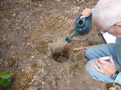
Step 3: Infiltration testing
Perform the actual infiltration test(s) to determine soil infiltration rate(s).
Step 4: Design considerations
Collect and analyze the data to select, site, and size facilities in the development area.
It’s possible that additional infiltration testing will be needed after Step 4, since the designer may want to move a facility from a poorly infiltrating area to a better location. The number of infiltration tests for large sites varies widely with jurisdictional requirements but is also impacted by the variability in soil conditions across the site. In urban sites, where soils may have been disturbed a number of times over many years, soil conditions may vary greatly over small distances. In any case, test directly over or within close proximity to the proposed facility.
The LID Stormwater Manual Template for Western Oregon recommends one test per 10,000 square feet within large areas. Consult a licensed, qualified geotechnical engineer to help identify soil uniformity and the appropriate number of tests.
Presoaking
Before conducting a field test, you may need to presoak the soil by adding water to the test pit prior to taking measurements. How long you soak the soil before measuring depends on the choice of LID facility and environmental conditions.
Infiltration rates vary with the moisture content of the soil. Water added to dry soils will be absorbed and conveyed through the soil column faster than water added to already moist soils. In some regions of the country, the U.S. Environmental Protection Agency requires presoaking prior to percolation testing for wastewater systems in order to simulate the constantly wet conditions that a septic field receiving regular wastewater flows would have to absorb. In the rainy season in Oregon, presoaking may not be necessary.
During the dry season, presoak your test hole to simulate an LID facility in wet soil that has already received rainfall.
No one knows for sure how much presoaking is needed to simulate soil infiltration rates during the wettest month of the year; literature suggests numerous values. Soil type may also impact presoaking duration. Consult a geotechnical engineer or soil scientist for site-specific recommendations.
Types of tests
Percolation, modified percolation, and double-ring infiltrometer are three types of field tests used to determine infiltration rates. In addition, a laboratory method relates sieve analysis results to an infiltration rate.
The Washington State Department of Ecology (WSDOE) recommends the more extensive Pilot Infiltration Test (PIT), when possible, because it provides the most accurate estimate of infiltration; however, this test can take up to 17 hours, requires a lot of water, and is rarely used in Oregon. Find more information on the Pilot Infiltration Test in Chapter 3 of the Stormwater Management Manual for Western Washington.
According to the WSDOE, both the double-ring infiltrometer test and percolation test overestimate infiltration rates (WSDOE 2005). Additionally, the double-ring infiltrometer is an expensive piece of equipment and is generally used only by geotechnical professionals; however, a version made from parts found at a hardware store can be made to simulate the tool.
The following tests yield an infiltration rate in inches per minute. Don’t forget to convert to inches per hour, which is the industry standard for modeling and designing. Also, apply a factor of safety or correction factor (often represented as FS or CF) to the tested infiltration rate to arrive at a design infiltration rate with a lower value than the tested infiltration rate. This factor depends on site conditions, expected levels of maintenance, and the type of facility. In some cases, designers choose not to use a factor of safety. Consult a geotechnical engineer or designer as well as your local jurisdictional engineering department to establish appropriate design infiltration rates for your project.
Percolation tests
A percolation test allows water to infiltrate, correcting the final infiltration rate with an adjustment factor. These tests are generally applicable to any surface infiltration facility, but they are used by some consultants for drywells in soils where a modified percolation test isn’t feasible.
Two types of percolation tests, the falling head test and the reduction factor test, are described below.
Falling Head Test
The falling head test is one of the oldest and simplest methods, commonly used for designing septic fields. It has been used successfully on LID projects for over 30 years by professionals in the field. The following procedure is from the LID stormwater manual template for western Oregon (ODEQ 2016).
- Dig a test hole with a post hole digger or a larger area with a shovel. The area of the hole doesn’t matter. Dig a hole to the appropriate depth as discussed above.
- Perform a ribbon test to determine soil texture.
- If soils are clayey, scrape, or “scarify,” the sides of the hole a little. Remove the scraped material from the bottom of the hole and place an inch or so of clean gravel at the bottom; otherwise, the tiny clay particles will be suspended in the water to follow and form an impermeable barrier (appearing as a sheen) around the sides and bottom of the hole.
- Push a pencil or nail into the side of the hole from which to measure the water level drop over time. The height above the bottom of the hole (or gravel if included) will determine the water level depth. Because water is so heavy, deeper water will result in faster overall infiltration rates, so this is accounted for in the following: Runoff prevention. Place the pencil or nail 6 inches above the bottom of the hole.Runoff reduction. The depth of water should reflect the amount of water that might be ponded in a runoff reduction BMP. For instance, if the ponding depth will be 9 inches, then place the pencil or nail 9 inches above the bottom of the hole. If the ponding depth is unknown, 6 inches is a conservative depth.
- Gently fill the hole with water to the top of the pencil or nail. Record the exact time you stop filling the hole and the time it takes to drain completely. If soils are fast draining, measure time down to the second.
- If testing during the rainy season and soils are saturated, go on to step 7. If testing during the dry season and soils are dry, refill the hole again and repeat steps 2 to 5 two more times. Averaging the results of the third test will give you the best measure of how quickly your soil absorbs water when it is fully saturated, as it would be during a rainy period of the year or during a series of storms that deliver a lot of rainfall in a short period of time. Occasionally, due to water changing the soil structure, infiltration rates can increase over short time periods during the test. But on average, the infiltration rate should generally decrease with each round.
- To calculate the infiltration rate, divide the distance that the water dropped by the amount of time it took for it to drop. For example, if the water dropped 6 inches in 12 hours, then 6 divided by 12 equals 0.5 inches per hour.
- If testing is for porous pavement managing direct rainfall only, skip to step 9. For rain gardens, stormwater planters, and porous pavements managing runoff, if the slowest infiltration rate measured is less than 0.5 inches per hour, then dig another hole nearby, but 3 to 6 inches deeper, and repeat steps 1 to 5 to see if there’s a faster-draining soil that could be overexcavated to. Repeat this process at various depths down to another 2 feet, or until you have at least 0.5 inches per hour infiltration. If you can’t find a suitable area with an infiltration rate of at least 0.5 inches per hour, infiltration BMPs must be designed and modeled by a qualified licensed engineer. Skip to step 10.
- For porous pavements that infiltrate rainfall, if the slowest infiltration rate measured is less than 0.3 inches per hour, consider relocating the porous pavement to a faster-draining soil. If this is not possible and the infiltration rate below the porous pavement managing rainfall only is less than 0.3 inches per hour, then the porous pavement must be modeled by a qualified licensed engineer.
- Confirm vertical separation.
Meet these two conditions for vertical separation:
- After infiltration testing is complete, dig the hole another 2 feet of depth from the bottom of the BMP (the elevation where water will begin to pond) to uncover bedrock or other impermeable subsurface layers, such as compacted ash, that may impede infiltration. If the soil is pretty consistent all the way down then one criteria for vertical separation is met.
- If testing during the winter, dig the hole 1 foot deeper to discover groundwater. If water doesn’t seep into the hole, then groundwater is sufficiently deep and the second vertical separation criteria is met. If not testing during the winter, hire a registered soil scientist, licensed geotechnical engineer, registered geologist, or other qualified licensed professional to assist with assessing the depth of the seasonal high groundwater table.
Refill the hole and leave the site in a safe condition. Work to prevent tripping hazards.
Reduction Factor Method percolation test
Site preparation: In an area in or near the proposed stormwater facility, excavate evenly a hole 6 to 10 inches in diameter to the elevation of the bottom of the proposed facility (typically 8 to 12 inches deep). This is most easily done with a posthole digger but can be done by hand. Because the digging process tends to consolidate the sides of the hole and this testing procedure readjusts the infiltration rate to account for water flows through the sides of the facility, scratch the bottom and sides of the soil surfaces with a sharp tool. Measure and record this diameter for final calculations. Remove excess soils resulting from scratching the soil (LIDMM 2008).
Water added during the test can also cause scouring and clogging of pores. To prevent these problems, place 2 inches of coarse sand or fine gravel in the bottom of the hole (LIDMM 2008) and pour water carefully so that it doesn’t hit the sides of the hole.
Presoaking: Before beginning the infiltration test, presoak the test area for an hour in total, and establish a measurement interval time. Measure at least 6 inches above the soil surface in the pit and mark this level with a nail, stake, or pencil. Fill the hole with water to the marker level. Keep filling the hole as needed to maintain the approximately 6-inch water depth for the next 30 minutes (LIDMM 2008).
In the last 30 minutes of the soaking hour, do not add water. If the pit contains no water after the 30 minutes, use a 10-minute measurement interval for testing. If water remains in the pit, use a 30-minute interval (LIDMM 2008). In Oregon, where soil is a mixture of clay and sand, the clay particles can easily be suspended in the presoaking water and clog, “or cement up,” the sides of the facility. These soils may also cave—an indication to seek out another location on the site, since these soils will likely fail in the same way once an infiltration facility is built over them.
Testing: Refill the hole to the marked water depth, which should approximately equal the expected ponding depth of the proposed facility. Filling to a water depth that exceeds the proposed ponding depth will skew results since pressure due to the additional depth of water, known as “head,” will increase the infiltration rate. Using the established interval times and from a fixed reference, measure and record the drop in water level. After each recording, stop the timer, refill the pit to the marker level and restart the timer. When eight readings have been collected, or when the drop in water level stabilizes (when the highest and lowest measurement within four consecutive readings is no more than a ¼-inch difference), no more measurements are required (LIDMM 2008).
Design infiltration rate: Determine the field infiltration rate, referred to below as the percolation rate, by averaging the measurements taken during the stabilized rate period, expressed in inches per hour (LIDMM 2008). Use this equation to correct for horizontal water infiltration:
Design infiltration rate = (percolation rate)/(reduction factor)
where:
Percolation rate is calculated from the measurements taken during the stabilized rate period.
Reduction factor (Rf) = ((2d1 - ∆d)/(DIA)) + 1
where:
d1 = Initial water depth (in)
∆d = Percolation rate (average water level drop) (in)
DIA = Diameter of the percolation hole (in)
The reduction factor will vary depending on hole size. Wider and shallower tests have lower reduction factors because proportionately less water is absorbed by the soil on the surrounding sides. The percolation test assumes that there is uniform soil across the surface of the pit, and water depth affects the percolation rate. If these assumptions are not true for your site, consider using additional adjustments (LIDMM 2008).
Modified percolation testing
In one alternative to open hole percolation testing, a 6-inch solid pipe is driven into native soils until it is properly seated to form a seal. Presoaking and testing guidelines should be performed as discussed above, but in this case, water is only infiltrating out the bottom of the pipe and no reduction factor is needed to adjust for hole depth and diameter. The geotechnical engineer or soil scientist may still recommend a factor of safety for other variables.
Testing deep soils for drywells: Drywells are good candidates for the modified percolation testing method. First, excavate the first few feet. Then, a deeper hole can be hand augered, machine drilled, or backhoed with a clamshell to the proposed bottom of the drywell. A solid pipe can then be seated and used for testing. Since a drywell is vertical, pressure builds as the depth of the water increases, causing more water to be pushed out the sides. This phenomenon, known as pressure head, plays a more prominent role in dictating drywell infiltration rates than it does for other facilities. Some consultants choose to test conservatively by using floats to maintain no more than 12 inches of water; others use a depth of water that’s convenient for them to test while they stand at the surface (but that depth should not exceed the depth of water that will actually be accumulating in the drywell during large storms).
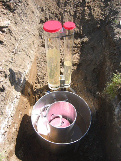
Double-ring infiltrometer test
In a double-ring infiltrometer test the vertical infiltration rate is isolated. Since water moves out through the sides of a facility as fast as through the bottom in most cases, this test is good for facilities such as rain gardens that primarily infiltrate through the bottom. However, this test may underestimate infiltration rates from facilities such as soakage trenches and drywells.
An inner ring is used to measure water drop over time, and an outer ring minimizes lateral water movement from the inner ring. The test can be performed at different depths, but the rings must penetrate at least 2 inches below the ground surface. At least 6 inches of both cylinders must be above the surface. (The cylinder should be a minimum of 8 inches high.) If the proposed infiltration facility will pond water to a depth greater than 6 inches, taller rings will be needed to simulate the greater depth. Test kits can be purchased or fashioned with supplies found at most local hardware stores (LIDMM 2008).
The double-ring infiltrometer test measures the infiltration rate of a very small and specific area. Multiple measurements at different areas of the site may be needed to properly assess suitability (PSAT 2005).
Supplies
- Two impermeable cylinders. The inner ring should be no smaller than 4 inches in diameter and equal to 50 to 70 percent of the outer ring diameter. For example, an 8-inch inner ring with a 12-inch outer ring.
- Water source
- Timer
- Measuring device (ruler, measuring tape)
- Flat wooden board that covers diameter of cylinders. This will be used to push the cylinders into the ground.
- Rubber mallet
- Log sheets and writing utensil or computer
The City of Portland requires that the double-ring infiltrometer test follow ASTM 3385-94 standards (PSMM 2016). However, many municipalities require modified versions of ASTM which often take less time. Check with your local jurisdiction for appropriate procedures. Basic steps are described below.
Site preparation: In an area in or near the proposed site, excavate to the depth of the bottom of the proposed facility.
Evenly drive the larger outer ring at least 2 inches into the ground by setting the flat wooden board atop the cylinder and firmly striking it with the rubber mallet (LIDMM 2008). Make sure at least 6 inches of the cylinder is above the ground.
Center the inner ring within the outer ring and follow the same procedure as above with the wooden board and mallet. Make sure the bottoms of both rings (underground) are at the same depth (LIDMM 2008). You can test different depths or strata by excavating a pit area, but make sure the rings are easily accessible and water can easily be added over a period of hours.
Presoaking: Before beginning the infiltration test, presoak the test area and establish a measurement interval time. To presoak the area, fill the inner and outer rings to the brim or water level mark. Keep the water level above 4 inches for 30 minutes. At the end of 30 minutes completely refill the rings.
Measure the water depth in the inner ring and wait another 30 minutes. Measure the water depth again to determine the drop in water level. If equal or greater to 2 inches, use 10-minute intervals. If less than 2 inches, use a 30-minute interval (LIDMM 2008).
Testing: Fill the rings to the brim or water level. Using the established interval times and from a fixed reference, measure and record the water level drop in the inner ring at each interval. After each recording, stop the timer, refill the rings and restart the timer. When eight readings have been collected or the water level drop stabilizes (when the highest and lowest measurement within four consecutive readings is no more than a ¼-inch difference), no more measurements are required (LIDMM 2008).
Design infiltration rate: Determine the infiltration rate of the test area by averaging the measurements taken during the stabilized rate. This should be expressed in inches per hour (LIDMM 2008).
Laboratory testing
Infiltration rates are directly related to a soil’s grain size distribution, which is the range and percentage of soil particle diameters. Soils with small grains such as clays and silts will drain slower than soils with large grains such as sands and gravels. In particular, the percentage of clay, which expands as it soaks up sizable amounts of water, reduces infiltration rates. Silts, which may be the same size as clay, can actually have relatively high infiltration rates. Field testing in pockets of silt in Washington County, Oregon, have yielded results between 20 and 45 inches per hour, while clay and clay silts in other parts of the county infiltrate at 0.5 inches per hour.
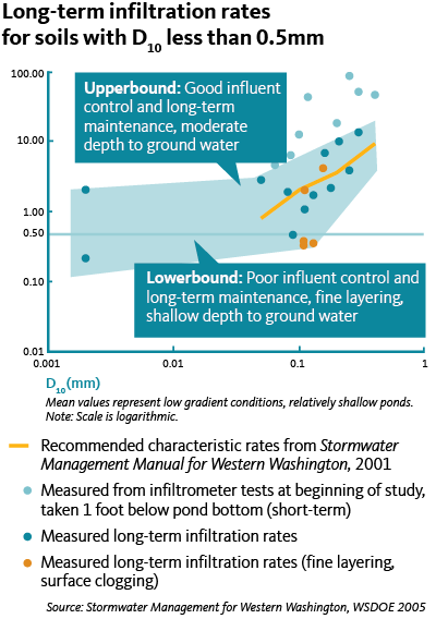
Washington State Department of Ecology has developed two methods that correlate grain size distribution to infiltration rates: the USDA Soil Textural Classification and ASTM Gradation Testing at Full Scale Infiltration Facilities. Because the ASTM method has been calibrated to full-scale infiltration testing of existing LID facilities, we’ll discuss this method briefly here. For more information on both methods, see Volume 3, “Hydrologic Analysis and Flow Control Design/BMPs” of the Stormwater Management Manual for Western Washington.
To determine the infiltration rate of a soil using this method, collect a representative sample. (The sample is expected to have the same grain size distribution as the soil left in place.) Different soils may require different volumes of soil to gather a representative sample. Send the sample to a soil testing lab and request an ASTM D422 procedure. The lab will dry the soil out and run a series of tests on it, including a sieve analysis to assess the volume of the soil’s smallest 10 percent particles, or D10. See the table and graphic on for guidelines on determining long-term infiltration rates for soils of specific particle sizes.
Long-term infiltration rates for soils with D10 greater than 0.05mm
D10 size from ASTM D422 soil gradation test (mm)
Estimated long-term (design) infiltration rate (inches/hour)
≥ 0.4
9
0.3
6.5
0.2
3.5
0.1
2.0
0.05
0.8
Since these infiltration recommendations represent long-term design infiltration rates and not field-tested infiltration rates, no factor of safety is needed unless there is no pretreatment system for sediments, less than average maintenance is expected, or soil horizons are finely layered.
References and resources
Oregon Department of Environmental Quality (ODEQ). 2016. Low-impact Development in Western Oregon: A Practical Guide for Watershed Health. www.oregon.gov/deq/wq/tmdls/Pages/TMDLs-LID.aspx
Puget Sound Action Team (PSAT) and Washington State University Pierce County Extension. 2005. Low Impact Development: Technical Guidance Manual for Puget Sound. Publication No. PSAT 05-03. Olympia, WA.
Southeast Michigan Council of Governments. 2008. Low Impact Development Manual for Michigan: A design guide for implementers and reviewers. Detroit, MI.
Washington State Department of Ecology (WSDOE) Water Quality Program. 2005. Stormwater Management in Western Washington: Volume III: Hydrologic Analysis and Flow Control Design/BMPs. Pub. No. 05-10-31. Olympia, WA.
Washington State Department of Transportation (WSDOT). 2008. Highway Runoff Manual. Publication No. M 31-16.01. Olympia, WA,.
Washington State Department of Transportation. (n.d.). Stormwater Research—Reports. Retrieved Feb 2009. http://www.wsdot.wa.gov/Environment/WaterQuality/Research/Reports.htm
Determine soil texture with a Ribbon test
To properly implement an infiltration facility, identify the approximate soil texture of your existing native soils, which may range from more sandy to more clayey.
- Take a handful of the soil you have excavated from your infiltration test. Pulverize it in your hand and remove any bits of organic matter or obvious rocks.
- Wet it with a small amount of water and rub it between your thumb and index finger. Don’t saturate it until it is runny mud. You might feel stickiness, grittiness, or smoothness. The grittier the feel, the more sand is present in your soil. The slicker the soil, the more clay in it. Smooth soils are sometimes an indicator of a fine silt or loam. Discard the soil.
- Next, take another sample in your hand. Wet it until it has the consistency of dough. You should be able to form a ball that holds together with the soil in your palm. If you cannot get the ball to form, then your soil is very sandy. In most soils, however, you should be able to create a rough ball.
- Knead the soil between your thumb and fingers and attempt to form a ribbon. As you build the ribbon, it will either hold together or break off.
- Interpret your results.
- If the soil forms a ribbon less than 1 inch in length before it breaks, the soil is sandy or silty.
- If the ribbon is 1 to 2 inches in length, the soil is clayey (that is, it has some clay).
- If the ribbon is greater than 2 inches before it breaks, the soil is clay.
© 2018 Oregon State University.
Extension work is a cooperative program of Oregon State University, the U.S. Department of Agriculture, and Oregon counties. Oregon State University Extension Service offers educational programs, activities, and materials without discrimination on the basis of race, color, national origin, religion, sex, gender identity (including gender expression), sexual orientation, disability, age, marital status, familial/parental status, income derived from a public assistance program, political beliefs, genetic information, veteran’s status, reprisal or retaliation for prior civil rights activity. (Not all prohibited bases apply to all programs.) Oregon State University Extension Service is an AA/EOE/Veterans/Disabled.
About the authors